1-3
Rear panel
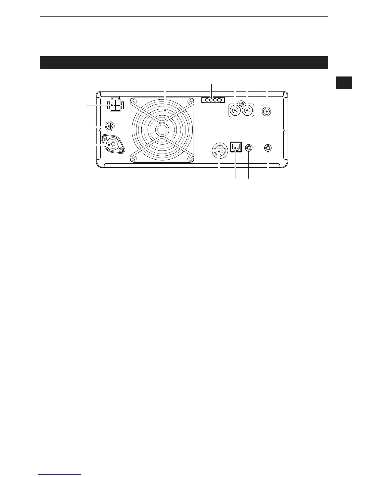
q DC POWER SOCKET [DC 13.8 V] (p. 2-2)
Accepts 13.8 V DC through the DC power cable.
w GROUND TERMINAL [GND] (p. 2-1)
Connects to ground to prevent electrical shocks,
TVI, BCI and other problems.
e ANTENNA CONNECTOR [ANT] (p. 2-2)
&RQQHFWVWRDȍ3/FRD[FRQQHFWRU
r SOCKET [ACC] (p. 2-2)
Connects to devices to control an external unit or to
control the transceiver.
t USB PORT (B TYPE) [USB] (p. 2-2)
Connects to a PC.
y CI-V REMOTE CONTROL JACK [REMOTE]
(p. 2-2)
• Connects to a PC or other transceiver for external
control.
u EXTERNAL SPEAKER JACK [EXT-SP] (p. 2-2)
$FFHSWVDaȍH[WHUQDOVSHDNHU
i KEY JACK [KEY] (p. 2-2)
Connects to a straight key, external electronic
NH\HURUDSDGGOHZLWKPP»VWHUHRSOXJ
o SEND CONTROL JACK [SEND] (p. 2-2)
Connects to control transmit with non-Icom external
units.
!0 ALC INPUT JACK [ALC] (p. 2-2)
Connects to the ALC output jack of a non-Icom
OLQHDUDPSOL¿HU
!1 TUNER CONTROL SOCKET [TUNER] (p. 2-2)
Accepts the control cable from an optional
AH-4 or AH-740
AUTOMATIC ANTENNA TUNER.
!2 COOLING FAN
Cools the PA unit when necessary.
q
w
e
r y ut
o!0!1 i!2

 Loading...


