2-3
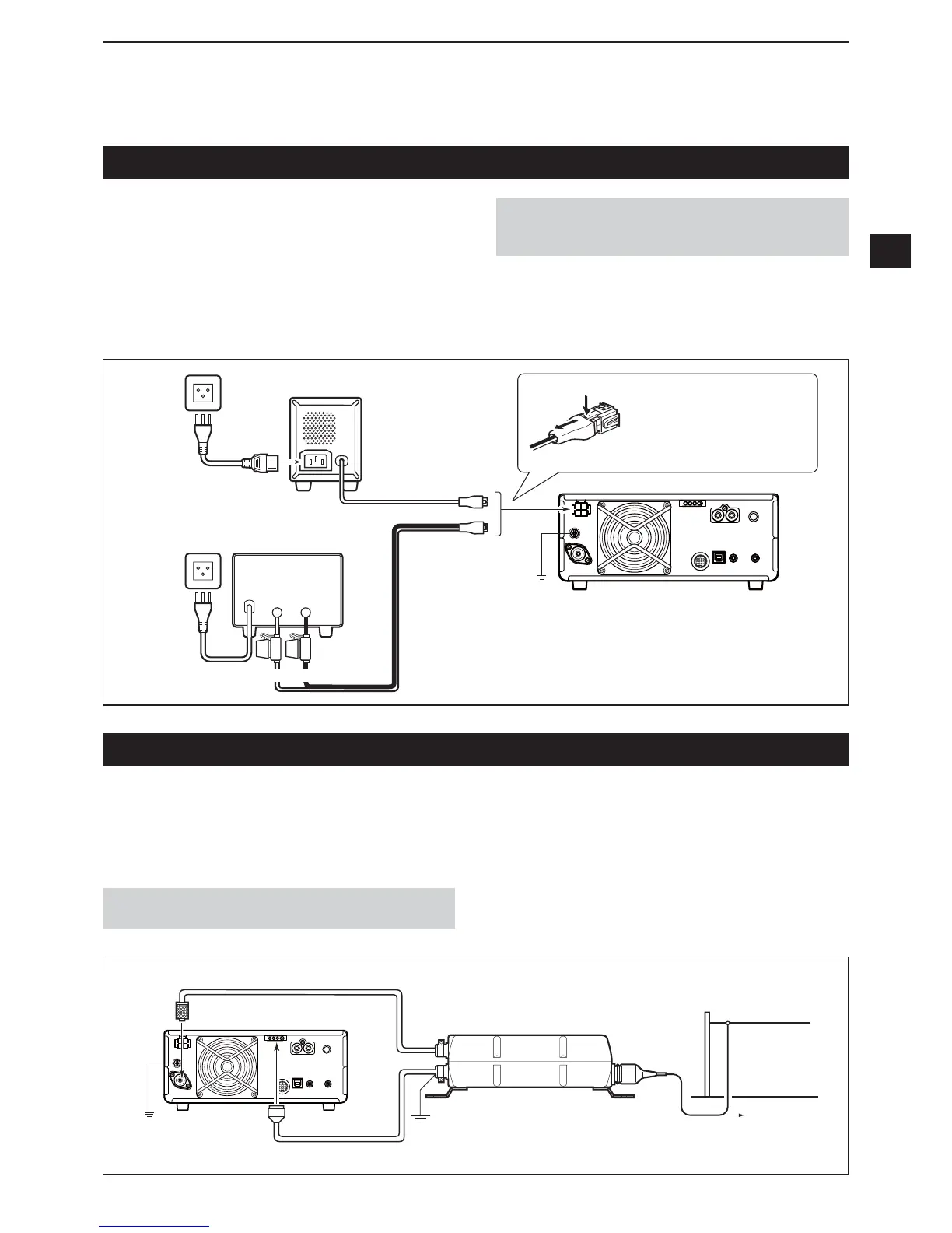
Connecting an external DC po er supply
&RQ¿UPWKDWWKHWUDQVFHLYHULV2))EHIRUHFRQQHFWLQJ
the DC power cable.
LWe recommend using Icom’s optional PS-126
(DC 13.8 V 25 A) power supply.
LWhen connecting a non-Icom DC power cable, the
transceiver needs
• DC 13.8 V (Capacity At least 21 Amps)
• a power supply with an over current protective line and
ORZYROWDJHÀXFWXDWLRQRUULSSOH
_+
PS-126
Non-Icom DC po er supply
PS-126
AC cable DC power cable
,&
q
w
:KHQGLVFRQQHFWLQJ¿UPO\
push down the locking tab
and then pull the connector
out of the socket.
GND
Supplied DC
power cable
BlackRed
Connecting the antenna tuner
The AH-4 AUTOMATIC ANTENNA TUNER matches the
,&WR
the optional AH-2b or a long wire antenna
PRUHWKDQPIWORQJEHWZHHQ0+]DQG
0+]
NOTE Before connecting, be sure to turn OFF the
transceiver power.
LSee the AH-4 instruction manual for installation and
connection details.
GND
AH-4
GND
[ANT]
,&
[TUNER]
HF band long wire
antenna
Or to an optional AH-2b
Control cable
Fuses
CAUTION
DO NOT touch the cooling fan on the rear panel
of the transceiver after transmitting continuously for long
periods of time. The transceiver becomes extremely hot.

 Loading...


