12
CONNECTOR INFORMATION
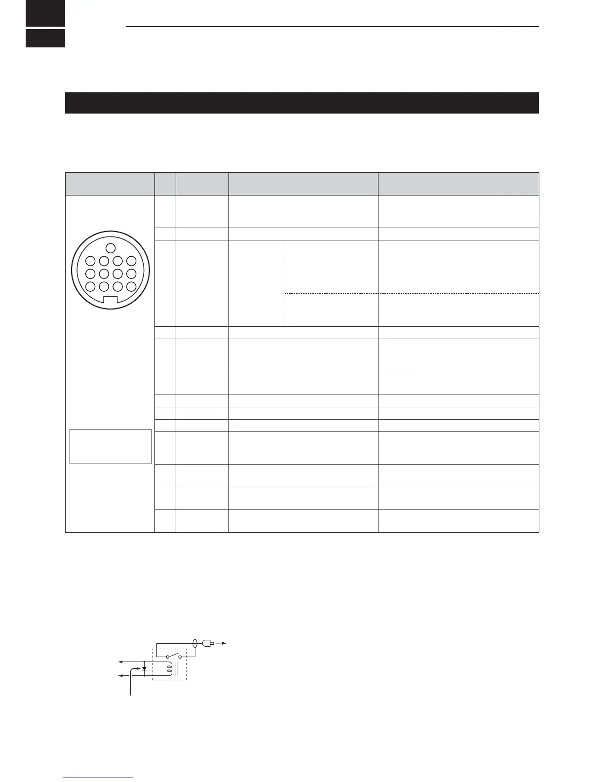
12-1
ACC soc et
Connects to external equipment or a PC to control the
external unit or to control the transceiver.
• ACC soc et
ACC
PIN
No.
NAME DESCRIPTION SPECIFICATIONS
18 V
Regulated 8 V output.
(Used as the reference voltage for the
band voltage.)
Output voltage
Output current
8 V 0.3 V
Less than 10 mA
2 GND Connects to ground.
3 SEND*
1
Input output
pin.
An external unit
controls the transceiver.
When this pin goes to
ground, the transceiver
transmits.
Input voltage (RX)
Input voltage (TX)
&XUUHQWÀRZ
2.0 to 20.0 V
0.5 to 0.8 V
Maximum 20 mA
7KHSLQJRHVORZ
ZKHQWKHWUDQVFHLYHU
transmits.
Output voltage (TX)
&XUUHQWÀRZ
Less than 0.1 V
Maximum 200 mA
4 BDT Not used.
5 BAND
Band voltage output.
9DULHVZLWKWKHVHOHFWHGDPDWHXU
band)
Output voltage 0 to 8.0 V
6 ALC ALC voltage input.
Input level
Input impedance
4 to 0 V
0RUHWKDQNȍ
7NC
8 13.8 V 9RXWSXWZKHQSRZHULV21 Output current Maximum 1 A
TKEY Not used.
10 FSKK Controls RTTY keying.
High level
/RZOHYHO
Output current
More than 2.4 V
Less than 0.6 V
Less than 2 mA
11
MOD Modulator input.
Input impedance
Input level
Nȍ
100 mV rms
*
3
12
AF IF
(IF 12 kH )*
2
Fixed AF detector or receive IF
(12 kH ) signal output.
Output impedance
Output level
Nȍ
100 ~ 300 mV rms
*
4
13 SQL S
Squelch output.
*URXQGHGZKHQWKHVTXHOFKRSHQV
SQL open
SQL closed
Less than 0.3 V 5 mA
0RUHWKDQ9ȝ$
13-pin
5HDUSDQHOYLHZ
qEURZQ
w red
e orange
r\HOORZ
t green
y blue
u purple
i gray
oZKLWH
!0 black
!1 pink
!2 light
blue
!3 light
green
Color refers to the
cable strands of the
supplied cable.
*
2
You can change the pin 12 setting in the “ACC USB
Output Select” item on the CONNECTORS set screen.
If the pin is set to IF, the transceiver outputs a 12 kH IF
signal from [ACC]. In that case, you can listen to the DRM
EURDGFDVWZLWKWKHDSSOLFDWLRQVRIWZDUHUHFHLYHUWKDWLV
installed into your PC.
*
3
You can change the input level in the “ACC MOD Level”
item on the CONNECTORS set screen. (p. 8-5)
100 mV rms is at the 50 (default) setting.
*
4
You can change the output level in the “ACC USB AF
Output Level” item on the CONNECTORS set screen.
(p. 8-5)
Approximately 200 mV rms is at the 50 (default) setting.
*
1
When the SEND terminal controls an inductive load, such
as a relay, a counter-electromotive force can malfunction
RUGDPDJHWKHWUDQVFHLYHU7RSUHYHQWWKLVZHUHFRPPHQG
DGGLQJDVZLWFKLQJGLRGHVXFKDVDQ66RQWKHORDG
side of the circuit to absorb the counter-electromotive force.
:KHQWKHGLRGHLVDGGHGDGHOD\LQUHOD\VZLWFKLQJPD\
RFFXU%HVXUHWRFKHFNLWVVZLWFKLQJDFWLRQEHIRUHRSHUDWLQJ
(Example) ACC socket
To a non-Icom
OLQHDUDPSOL¿HU
Relay
6ZLWFKLQJGLRGH
e SEND
i 13.8 V

 Loading...


