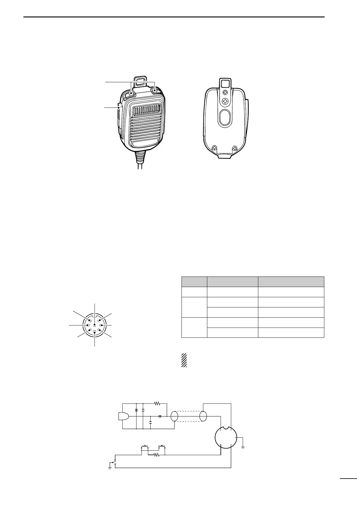
EasyManua.ls Logo

Icom IC-756 - Microphone (HM-36) Details

Icom IC-756
72 pages
To Next Page IconTo Next Page
To Previous Page IconTo Previous Page
Loading...
MICROPHONE CONNECTOR
(Front panel view)
CAUTION: DO NOT short pin 2 to ground as this
can damage the internal 8 V regulator.
y GND (PTT ground)
t PTT
r Main readout squelch switch
q Microphone input
w +8 V DC output
e Frequency up/down
u GND
(Microphone ground)
i Main readout AF output
(varies with [AF]/[BAL])
8
1
PANEL DESCRIPTION
Microphone (HM-36)
q UP/DOWN SWITCHES [UP]/[DN]
Change the selected readout frequency or memory
channel.
- Continuous pushing changes the frequency or memory
channel number continuously.
- While pushing [XFC], the transmit readout frequency
can be controlled while in spilt frequency operation.
- The [UP]/[DN] switch can simulate a key paddle. Preset
in the keyer set mode. (p. 35)
w PTT SWITCH
Push and hold to transmit; release to receive.
q
w
+
+
q
w
e
r
t
y
u
i
4700p
4700p
10µ
0.33µ
MICROPHONE
MIC
ELEMENT
2k
470
DOWN UP
PTT
RECEIVE
TRANSMIT
MICROPHONE CABLE MICROPHONE PLUG
HM-36 SCHEMATIC DIAGRAM
PIN NO. FUNCTION DESCRIPTION
w
+8 V DC output Max. 10 mA
e
Frequency up Ground
Frequency down Ground through 470
r
Squelch open LOW level
Squelch closed HIGH level

Table of Contents

Other manuals for Icom IC-756

Related product manuals