TIMER
POWER
TRANSMIT
PHONES
ELEC-KEY
MIC
TUNER MONITOR NB NR
MIC GAIN RF POWER COMP KEY SPEED BK-IN DELAY
AF RF/SQL BAL NR
APF
LOCKTX
RX
AUTO NOTCH
TWIN PBT
APF CW PITCH
S
Po
0
10
1
1
1.5
2
3
5
9
+20
+40
+60dB
25
50
100
%
∞
SWR
ALC
F-1
SSB
F-2 F-3 F-4 F-5
SPEECH LOCK
RIT/ TX
TXRIT CLEAR
CW RTTY AM FM
SPLIT
MP-W MP-R
DUAL
WATCH
VFO/
MEMO
MAIN/
SUB
CHANGE
1.8
1
3.5
2
7
3
10
4
14
5
18
6
21
7
24.5
8
28
9
GENE
・
50
0
F-INP
ENT
▲
▼
MW
M-CL
TS
XFC
HF/50MHz TRANSCEIVER
i756
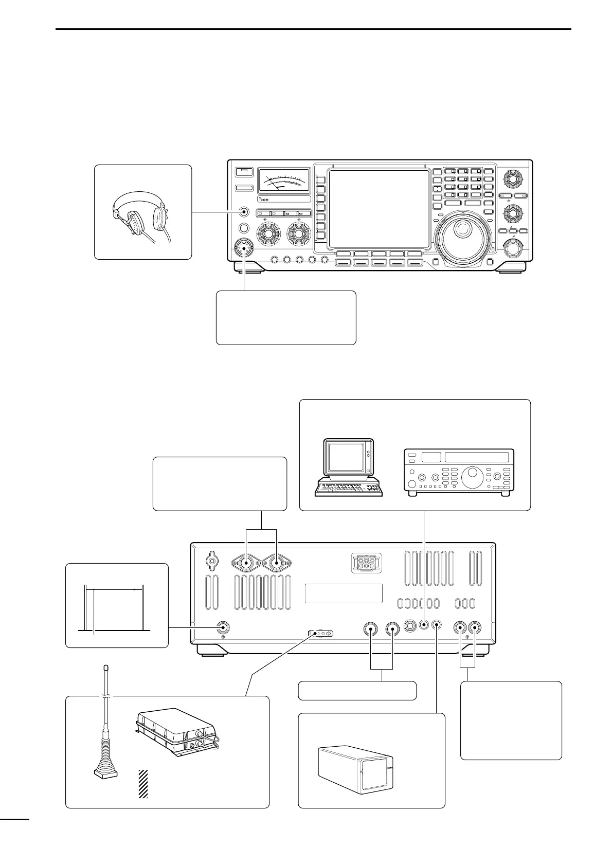
HEADPHONES
MIC
The AFSK modulation signal
can be input from [MIC]. (p. 19)
ANTENNA 1, 2 (pgs. 17, 18)
Connects a linear amplifier,
antenna selector, etc.
EXTERNAL SPEAKER (p. 68)
ACC SOCKETS (p. 12)
RX ANTENNA
SP-20
AH-3 (p. 18)
AH-2b
[REMOTE] (pgs. 20, 60)
Used for computer control and transceive operation.
[RELAY], [ALC]
(p. 17)
Used for connecting a
non-Icom linear ampli-
fier.
When using the AH-3, it must
be connected to the [ANT1]
connector.