12
1
PANEL DESCRIPTION
!1 ANTENNA CONNECTOR 1 [ANT1]
!2 ANTENNA CONNECTOR 2 [ANT2] (pgs. 13, 14)
Accept a 50 Ω antenna with a PL-259 connector.
NOTE: When using an optional AH-3 HF AUTOMATIC
ANTENNA TUNER, connect it to the [ANT1] connector.
The internal antenna tuner activates for [ANT2] and
deactivates for [ANT1] when connecting the AH-3.
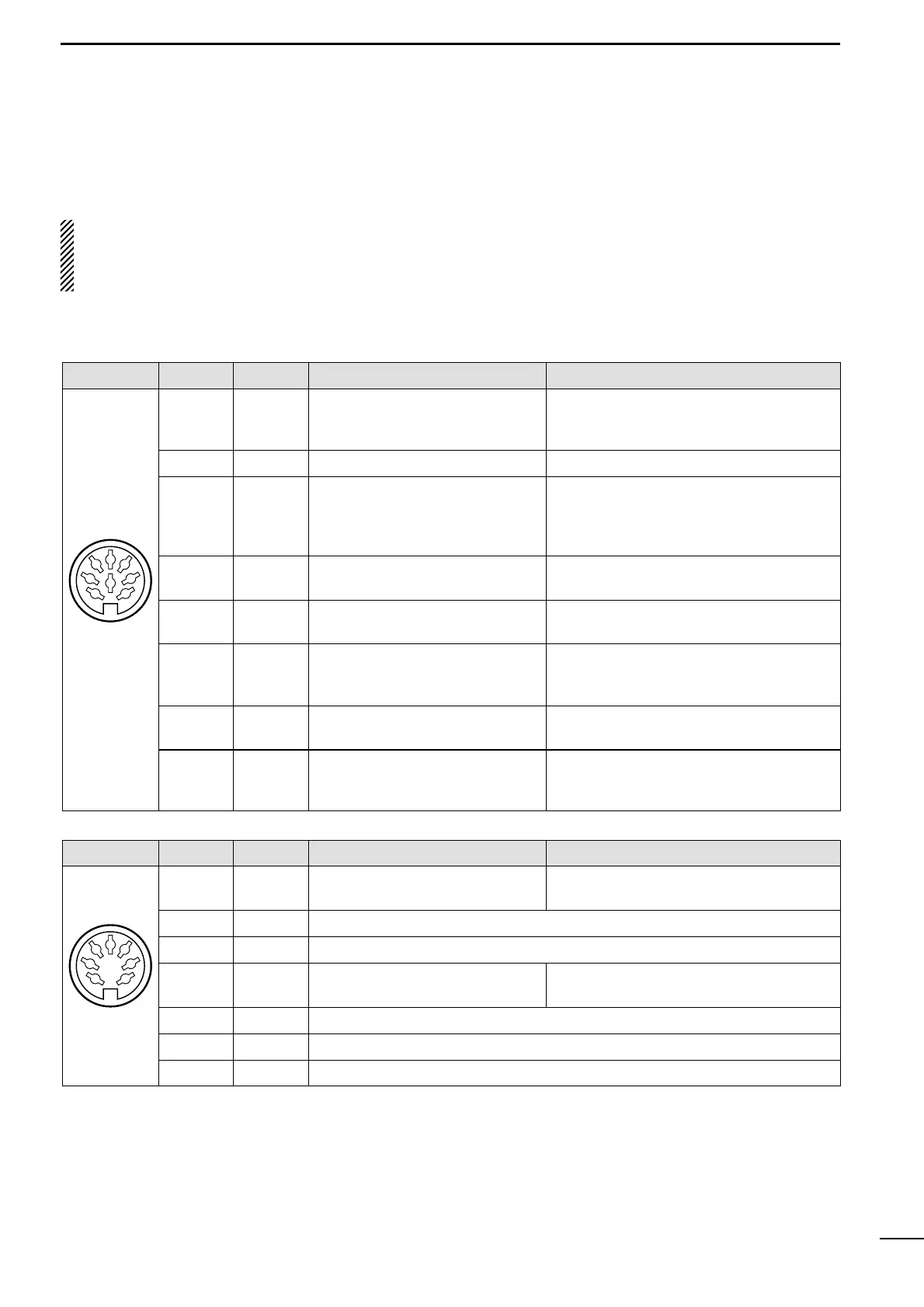
D ACC SOCKETS
!3 GROUND TERMINAL [GND] (pgs. 13, 14)
Connect this terminal to a ground to prevent electri-
cal shocks, TVI, BCI and other problems.
ACC(1) PIN NO.
PIN NAME
DESCRIPTION SPECIFICATIONS
1
RTTY Controls RTTY keying.
“HIGH” level : More than 2.4 V
“LOW” level : Less than 0.6 V
Output current : Less than 2 mA
2 GND Connects to ground. Connected in parallel with ACC(2) pin 2.
3 SEND
Input/output pin.
Goes to ground when transmitting.
When grounded, transmits.
Ground level : –0.5 V to 0.8 V
Output current : Less than 20 mA
Input current (Tx) : Less than 200 mA
Connected in parallel with ACC(2) pin 3.
4 MOD
Modulator input.
Connects to a modulator.
Input impedance : 10 kΩ
Input level : Approx. 100 mV rms
5 AF
AF detector output.
Fixed, regardless of [AF] position.
Output impedance : 4.7 kΩ
Output level : 100 to 300 mV rms
6 SQLS
Squelch output.
Goes to ground when squelch
opens.
Squelch open : Less than 0.3 V/5 mA
Squelch closed : More than 6.0 V/100 µA
7 13.8 V 13.8 V output when power is ON.
Output current : Max. 1 A
Connected in parallel with ACC(2) pin 7.
8 ALC ALC voltage input.
Control voltage : –4 to 0 V
Input impedance : More than 10 kΩ
Connected in parallel with ACC(2) pin 5.
Rear panel
view
1
2
3
4
5
6
7
8
ACC(2) PIN NO.
PIN NAME
DESCRIPTION SPECIFICATIONS
1
8 V Regulated 8 V output.
Output voltage : 8 V ±0.3 V
Output current : Less than 10 mA
2 GND Same as ACC(1) pin 2.
3 SEND Same as ACC(1) pin 3.
4 BAND
Band voltage output.
(Varies with amateur band)
Output voltage : 0 to 8.0 V
5 ALC Same as ACC(1) pin 8.
6 NC No connection.
7 13.8 V Same as ACC(1) pin 7.
Rear panel
view
1
2
3
4
5
6
7