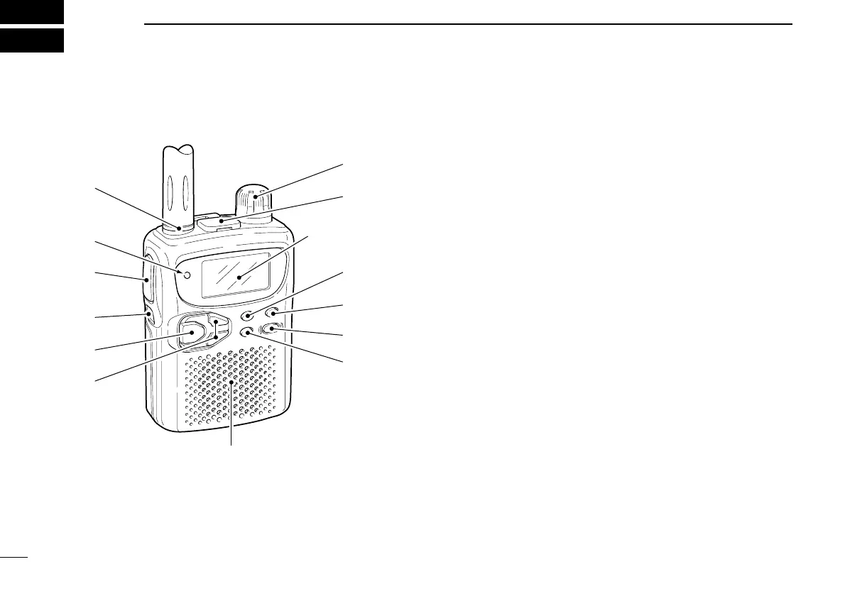
■ Panel description
q ANTENNA CONNECTOR (p. 1)
Connects the supplied antenna.
w TRANSMIT/RECEIVE INDICATOR [TX/RX] (p. 9)
Lights green while receiving a signal or when the squelch
is open; lights red while transmitting.
e PTT SWITCH [PTT]
➥Push and hold to transmit in 144/400 MHz amateur
bands; release to receive. (p. 9)
➥Push briefly, then push and hold to transmit a 1750 Hz
tone. (Europe and Italy versions only; p. 24)
r FUNCTION SWITCH [FUNC]
While pushing this switch, other switches and tuning dial
perform secondary functions.
•“Push [FUNC] + a switch” means “while pushing the [FUNC]
switch, push the switch.”
t BAND SWITCH [BAND]
➥Push to select the operating band (VHF, UHF, etc.). (p. 6)
•50 MHz band,* VHF avionics band,* 144 MHz band, 300 MHz
band,* 400 MHz band, 800 MHz band* and 1200 MHz band*
can be selected.
➥Transfers the displayed frequency to the VFO in mem-
ory mode. (p. 6)
➥Push [FUNC] + [BAND] to toggle the RIT function at 800
MHz* and above. (p. 8)
➥Push for 2 sec. to set the tuning step for the operating
band or the selected memory channel. (p. 7)
2
2
PANEL DESCRIPTION
(p. 4)