10
2
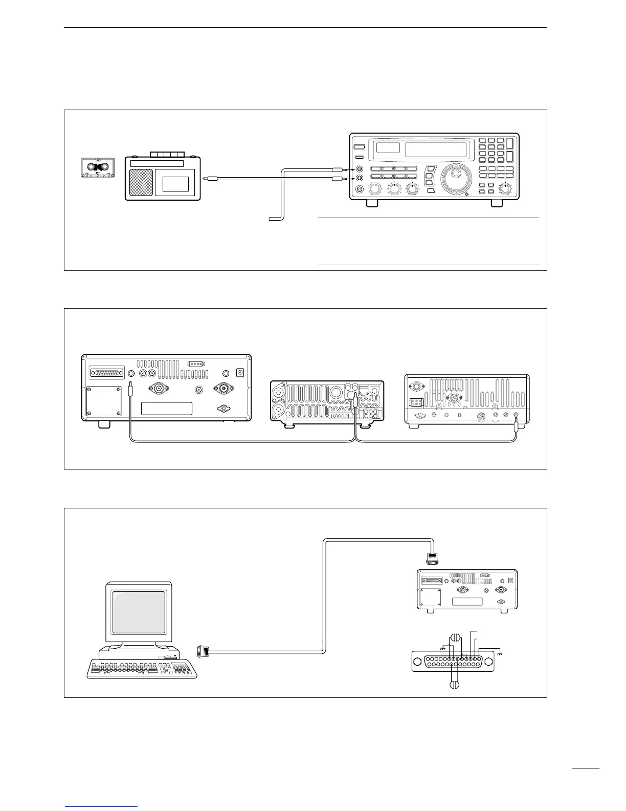
CONNECTIONS
■ Tape recorder connections
The [REC OUT] jack has 350 mV rms/4.7 kΩ output
for connection to other audio equipment.
■ Transceive function
Icom CI-V transceivers or receivers can be connect-
ed via the [REMOTE] jack. The frequency and mode
become the same* when either radio is changed.
*When a set frequency is out-of-range for one of the con-
nected transceivers or receivers, the connected radio’s
frequency/mode does not change.
■ Connecting to a PC
■ Data demodulation terminal
See p. 16 for details regarding connection and opera-
tion.
The IC-R8500 can connect directly to a personal
computer providing control of multiple functions such
as instant frequency/name programming using
appropriate software. See pgs. 35, 36 for the control
command table.
✔
Convenient:
When an optional UT-102
VOICE SYNTHESIZER UNIT
is
installed, detected frequencies during scanning can
be recorded. See pgs. 31, 32 for settings.
[REC REMOTE] jack:Grounds when a signal is
received and squelch opens. If a tape recorder has
a control terminal, this jack can be used for record-
ing control. (2 A/DC max.)
•Be sure the “CIV TRAN” item is turned ON in initial set mode (p. 32).
A DB9/DB25 adapter may be
required depending on the PC’s
connector.
 Loading...


