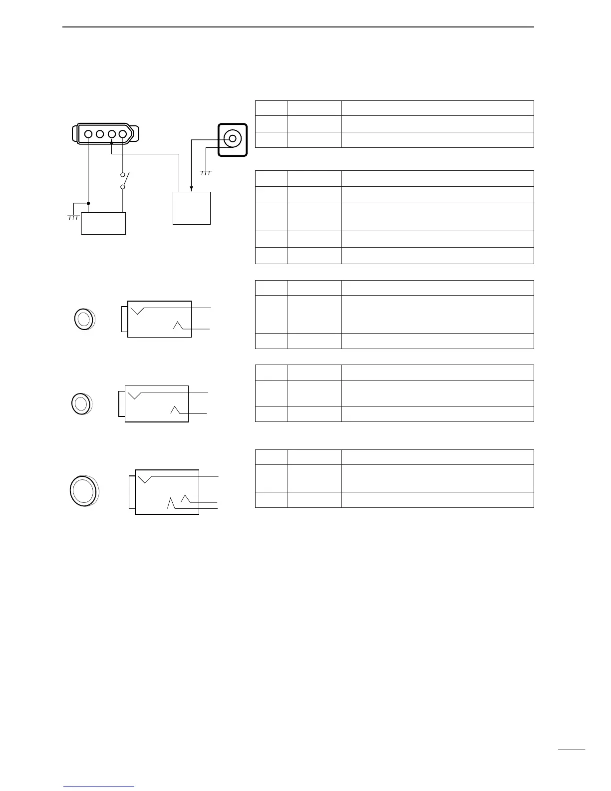
Pin Port name Description
Inner DC IN Accepts connection to the AD-55A/V only
Outer GND Grounded.
Pin Port name Description
1 13.8 IN 13.8 V DC input; current consumption 2 A
2 12.5 OUT
12.5 V DC output when connecting AD-55/A/V
to [DC IN] socket. Max. 2 A
3 NC —
4 GND Grounded.
Pin Port name Description
Inner SQL
•Grounded when squelch opens.
•Can be deactivated via initial set mode. (p. 31)
•Max. current:1 A/12 V DC
Outer GND —
Pin Port name Description
Inner DET
•Output detected audio output.
•100–300 mV rms/4.7 kΩ
Outer GND Grounded.
Pin Port name Description
Inner,
Middle
Audio
•Outputs audio.
•Output impedance:4–16 Ω
Outer GND Grounded.
 Loading...


