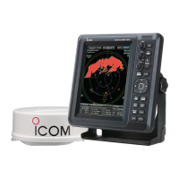
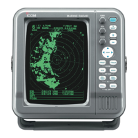
• SX-2713/SX-2779
MOB
POWER
TX
SAVE
TARGET
TRAILS
ZOOM
ALM
MODE
OFF CENT
EBL1
VRM1
PI
BRILL MENU
HL OFF
EBL2
VRM2
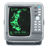
MARINE RADAR
269 (10.59) 258 (10.16)
48 (1.89)
264 (10.39)
287 (11.3)
132 (5.2)132 (5.2)
• Viewing hood installation
• SX-2713/SX-2779 Mounting Bracket
250 (9.84)
195 (7.68)
97.5 (3.84)
100 (3.94)
60 (2.36)
30 (1.18)
Ø7 (0.28)×4
Ø7 (0.28)
Fig. 1
• Mounting Bracket installation
Fig. 2
Self-tapping screw
Spring washer
Flat washer
Knob bolt
8
INSTALLATION AND CONNECTIONS
24
■ Installing the display unit
DLocation
Select a place for installation which meets the follow-
ing important conditions:
➥ The display unit should be placed near the wheel
in the cabin so that an operator may easily view the
radar screen while facing the bow.
➥ To minimize interference, KEEP the unit AT LEAST
THE COMPASS SAFE DISTANCE stated in the se-
rial number label on the rear panel away from the
compass and navigation receiver.
➥ Select a position where there is no danger of salt or
fresh water spray or immersion.
➥ Select a location where it is easy to perform mainte-
nance or adjustment after installation.
➥ Select a location which can support the weight of
the display unit.
➥ DO NOT select areas subject to extreme heat, cold,
vibrations or direct sunlight.
DMounting
The mounting bracket supplied with the display unit al-
lows “dashboard” or “overhead” mounting.
q Hold the mounting bracket up to the selected lo-
cation and mark pilot holes for the five installation
holes using the template.
• The template is provide on page 39.
w Drill five holes, 3 mm (0.12 in) in diameter as shown
in the diagram. (Fig. 1)
e Install the bracket using the knob bolts, self-tapping
screws or washers, with the supplied accessories.
(Fig. 2)
r Adjust the display unit to an adequate view angle.
t Install the supplied viewing hood.
 Loading...