Hardware
MVS6000 System Level Manual/1.0/Dec-2001 2-11
2.3 Camera Connections and Cables
Camera timing kits are programmable on the board. For each board two different timing kits can
be programmed.
Up to four standard resolution (SR) cameras or two high resolution (HR) cameras (ADIMEC), can
be connected to the MVS6000 board.
A combination of two SR cameras with one HR camera is also possible. In this configuration, the
same types of SR cameras must be connected to connector 1 and the HR camera must be
connected to connector 2.
Following figure summarizes the allowed combinations for the MVS6000 board:
Connector 1
Connector 2
SR
same
type
SR
SR
same
type
SR
HR
HR
SR
same
type
SR
HR
Note: Cameras may be missing in these configurations.
To connect:
· two SR cameras to one of the MVS connectors of the MVS600 board, a breakout box must be
used.
· four SR cameras to a MVS6000 board, two symmetrical breakout boxes must be used.
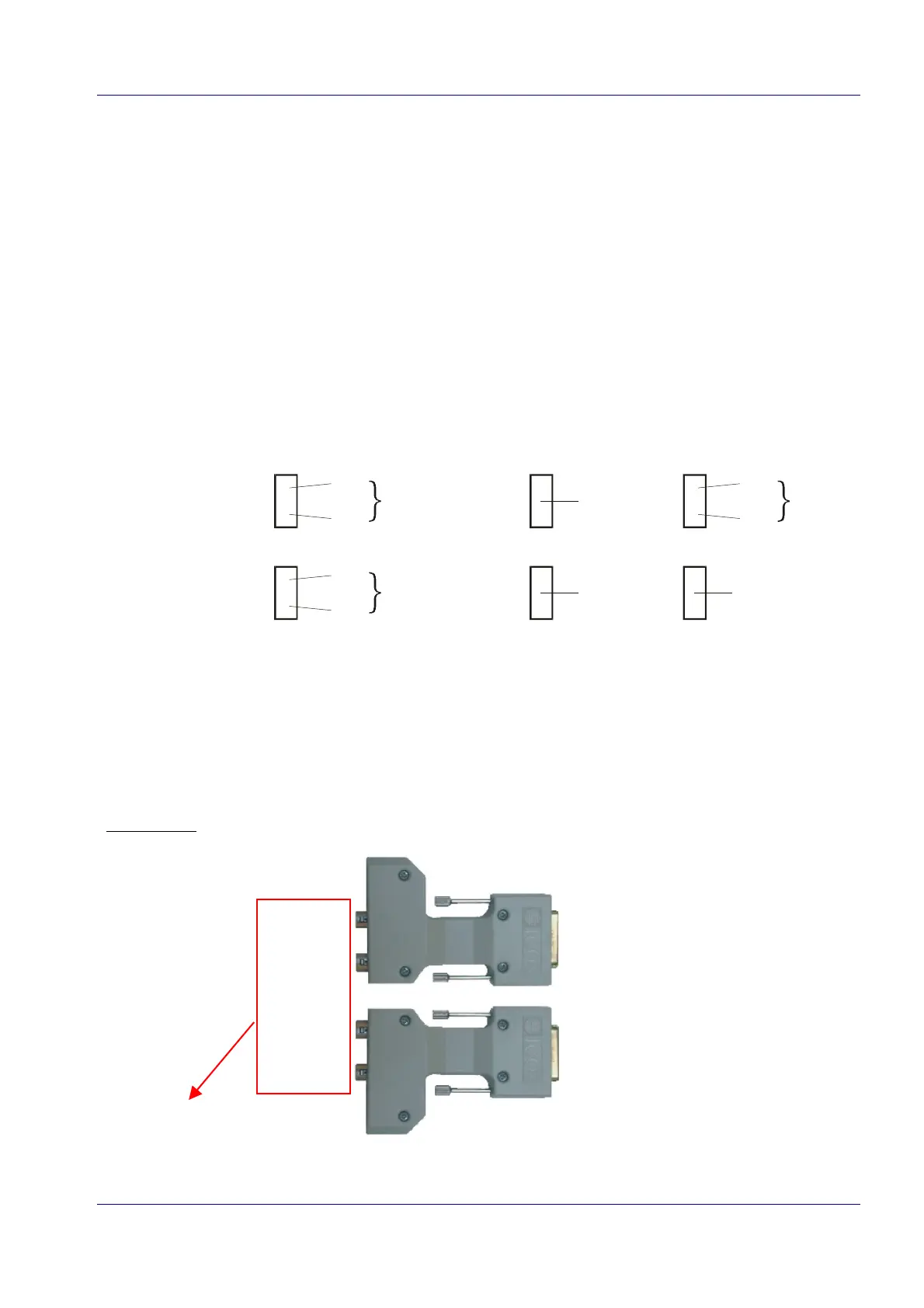
An example of two symmetrical breakout boxes (see also page 2-13).
to connector 1
of MVS6000
camera 2
camera 1
camera 4
camera 3
to connector 2
of MVS6000
camera numbering on
MVS6000 board (see
also page 3-23).