18
Installation and Servicing
SECTION 2 - INSTALLATION
V - See Diagram in
Section 1.16
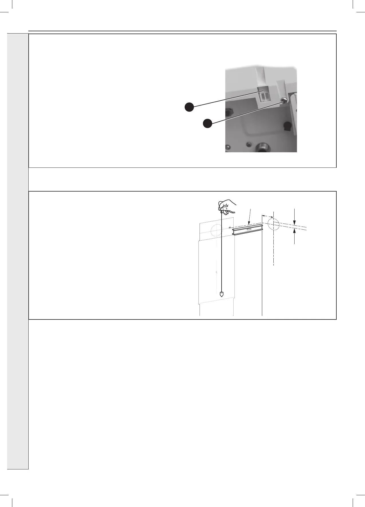
Extended centre line
155
The wall mounting template is located on the internal protective
packaging. The template shows the position of the xing and rear
ue centre holes for a standard installation
Care MUST be taken to ensure the correct holes are drilled.
1. Tape template into the required position, ensuring its squareness
by hanging a plumbline as shown.
2. If tting a side ue, extend the ue centreline onto the side by
155mm on a standard wall x.
3. Mark the following on to the wall:
a The selected group of wall mounting screw holes.
b. The centre position of the ue duct. Marking both the centre
and the circumference of the ue duct.
4. Remove the template plate from the wall.
2.6 WALL MOUNTING TEMPLATE
2.5 FRONT PANEL REMOVAL
1. Loosen the 2 screws retaining the front panel.
2. Pull the two clips downwards to disengage.
3. Pull the front panel forward and upwards to remove.
1
2