9
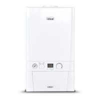
Installation and Servicing
SECTION 1 - GENERAL
1.9 FLUE INSTALLATION
Pluming will occur at the terminal so terminal positions where this could cause a nuisance should be avoided.
The ue must be installed in accordance with any local & state regulations and laws.
The following notes are intended for general guidance:
1. The boiler MUST be installed so that the terminal is exposed to external air.
2. It is important that the position of the terminal allows the free passage of air across it at all times.
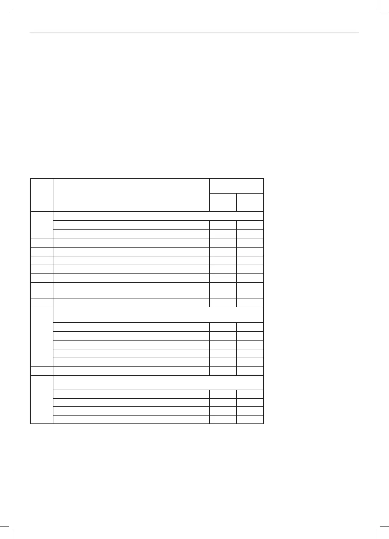
3. Minimum acceptable spacing from the terminal to obstructions and ventilation openings are specied in Table 4.
4. The ue assembly shall be so placed or shielded as to prevent ignition or damage to any part of any building.
IMPORTANT. It is essential to ensure, in practice, that products of combustion discharging from the terminal cannot re-enter the
building or buildings through any openings into the building such as ventilators, windows, doors, or other sources of natural air
inltration, such as forced ventilation openings etc.
If products of combustion re-entry is identied or suspected this should be immediately investigated and corrected following the
guidance provided by the local authority.
Ref. Item
Minimum
Clearances mm
Natural
Draught
Fan
Assisted
a
Below eaves, balconies and other projections:
For appliances up to 50 MJ/h input 300 200
For appliances over 50 MJ/h input 500 300
b From the ground, above a balcony or other surface * 300 300
c From a return wall or external corner * 500 300
d From a gas meter (M) (see Note 3) 1 000 1 000
e From an electricity meter or fuse box (P)
†
(see Note 3) 500 500
f From a drain pipe or soil pipe 150 75
g
Horizontally from any building structure * or obstruction facing
a terminal
500 500
h From any other ue terminal, cowl, or combustion air intake * 500 300
j
Horizontally from an openable window, door, non-mechanical air inlet, or any other
opening into a building with the exception of sub-oor ventilation:
Appliances up to 150 MJ/h input* 500 300
Appliances over 150 MJ/h input up to 200 MJ/h input* 1 500 300
Appliances over 200 MJ/h input up to 250 MJ/h input* 1 500 500
Appliances over 250 MJ/h input* 1 500 1 500
All fan assisted appliances, in the direction of discharge - 1 500
k From a mechanical air inlet, including a spa blower 1 500 1 000
n
Vertically below an openable window, non mechanical air inlet, or any other opening into a
building with the exception of sub-oor ventilation:
For space heaters up to 50 MJ/h input 150 150
For other appliances up to 50 MJ/h input 500 500
For appliances over 50 MJ/h input and up to 150 MJ/h input 1 000 1 000
For appliances over 150 MJ/h input 1 500 1 500
* Unless appliance is certied for closer installation.
†
Prohibited area below electricity meter or fuse box extends to ground level.
Notes:
1. Where dimensions c, j
or k cannot be achieved
an equivalent horizontal
distance measured
diagonally from the nearest
discharge point of the
terminal to the opening may
be deemed by the Technical
Regulator to comply.
2. For minimum clearances
not addressed above
acceptance should be
obtained from the Technical
Regulator.
3. Minimum clearances d
and e also apply to any
combustion air intake
openings of appliances.
Table 4 - Location of Flue Terminals of Balanced Flue, Room-Sealed, Fan Assisted or
Outdoor appliances (see diagram for illustrative purposes).