47
Installation and Servicing
SECTION 3 - SERVICING
1. Refer to Section 3.9.
2. Drain the heating system. Refer to Section
3.20.
3. Remove the boiler front (See Section 3.2),
lower the control panel and remove the
control box cover.
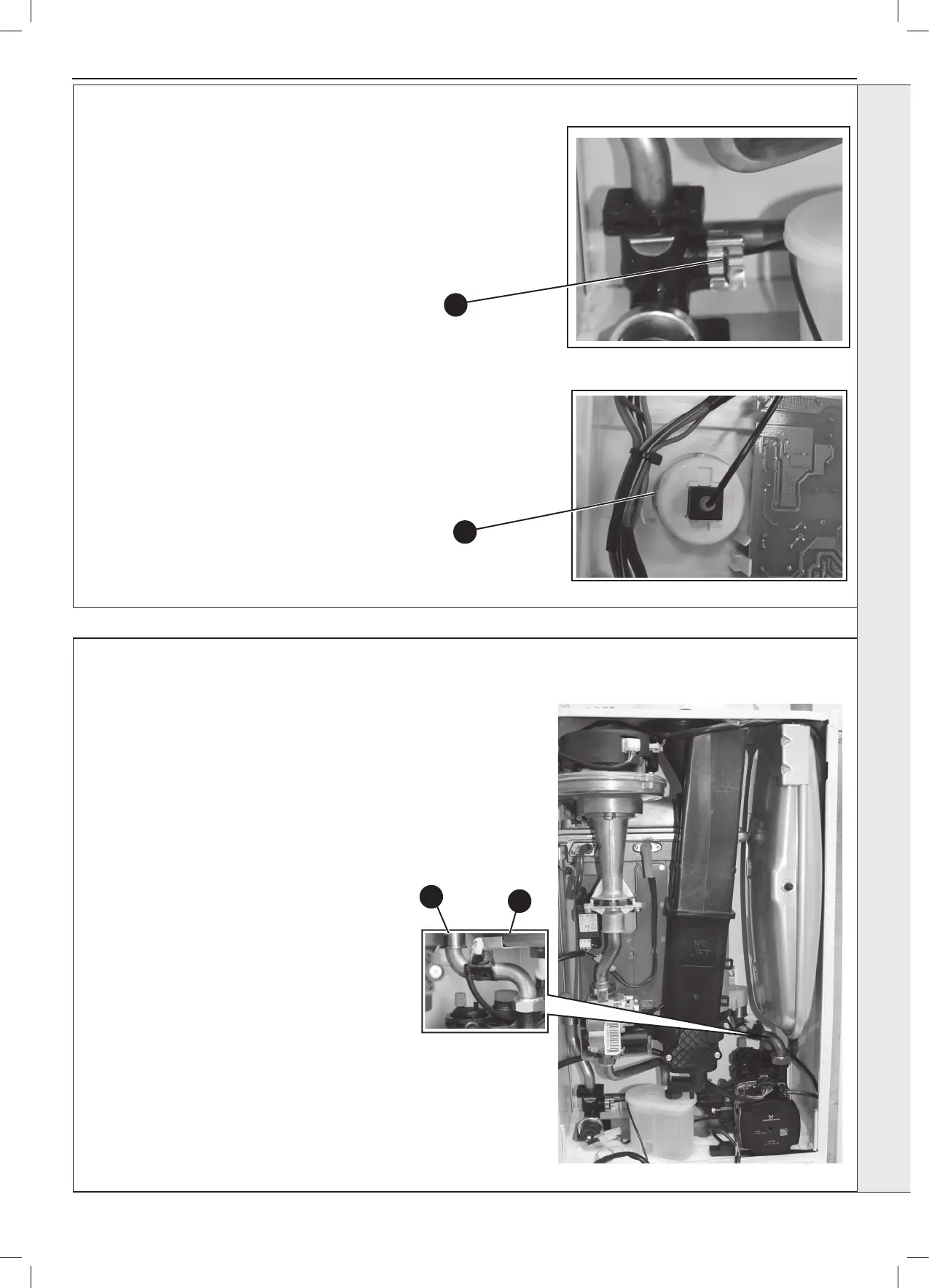
4. Ensuring there is no pressure in the system
unclip the C clip from the ow manifold port
and remove the capillary connection together
with ‘o’ ring.
5. Releasing the two retaining clips on the
pressure gauge ease the pressure gauge
through the front of the control panel.
6. Fit the new pressure gauge from the front of
the control panel ensuring correct orientation.
Locate push t connection into port ensuring
‘o’ ring in place and secure with the C clip.
7. Rell the boiler.
8. Check the operation of the boiler. Refer to
Sections 2.25 & 2.26.
3.21 PRESSURE GAUGE REPLACEMENT
5
4
3.22 SAFETY RELIEF VALVE REPLACEMENT
1. Refer to Section 3.9.
2. Drain the boiler. Refer to Section 3.20.
3. Remove the clip on return thermistor. Refer
to Section 3.13.
4. Pull out and remove the clip (positioned
behind the safety valve) retaining the safety
valve.
5. Undo the safety valve pipe compression
tting positioned outside the boiler casing.
6. Lift out the safety valve/pipe assembly.
7. Remove the safety valve pipe and transfer
to the new safety valve.
8. Reassemble in reverse order ensuring the
retaining clip is correctly tted, the pipe
compression tting retightened and return
thermistor is re-clipped.
9. Rell the boiler. Check operation of the
boiler. Refer to Sections 2.25 & 2.26.
3
4