36
Installation and Servicing
SECTION 3 - SERVICING
3 SERVICING
3.1 SERVICING SCHEDULE
For the very latest copy of literature for specication practices, visit our website www.huntheat.com.au, where you will be able to
download the relevant information.
WARNING. Always turn OFF the gas supply at the gas service cock, and switch OFF and disconnect the electricity
supply to the appliance before servicing.
Combustion testing must be carried out by a competent person using a combustion analyser.
To ensure the continued safe and efcient operation of the appliance it is recommended that it is checked at regular intervals and
serviced as necessary. The frequency of servicing will depend upon the installation condition and usage but should be carried out
at least annually.
Any service work must be carried out by a Licensed & Registered Engineer.
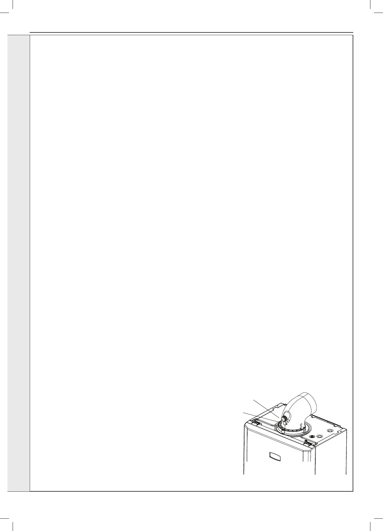
Flue Sampling Point
Air Sample
Point
Ensure all caps and seals
are re-fitted after use
IMPORTANT
1. If, for any reason, the condensate trap/siphon has
been removed, ensure the trap is relled with water
before re-assembling.
2. After completing the servicing or exchange of
components always ensure all gas valve connections
are gas tight with a gas soundness check up to the
gas control valve.
3. When work is complete the front panel MUST be
correctly retted, ensuring that a good seal is made.
4. Complete the service Section in the Commissioning
Checklist.General
Please Note: During routine servicing, and after any
maintenance or change of part of the combustion circuit,
the following must be checked:
- The integrity of the ue system and the ue seals
- The integrity of the boiler combustion circuit and the
relevant seals
- The operational (working) gas inlet pressure at
maximum rate
- The gas rate
- The combustion performance
Note. In order to carry out either servicing or replacement of components
the boiler front panel must be removed. Refer to Section 3.2.
PRELIMINARY INSPECTION
1. Light the boiler and carry out a pre-service check, noting any
operational faults (refer to appropriate fault nding chart as
necessary).
2. Check the ue terminal (and terminal guard if tted) is undamaged
and clear of any obstruction.
3. Check combustion by connecting the ue gas analyser to the ue
gas sampling point as shown in the diagram and measure CO and
CO
2 at maximum rate. To set the boiler to Maximum and Minimum
heat inputs see Page 35. Repeat at minimum rate.
If the CO / CO
2 ratio is greater than 0.004 please proceed to
“Cleaning Procedure”.
If the CO / CO
2 ratio is less than 0.004 please proceed to
“Check Procedure”.
CHECK PROCEDURE
1. Check all water and gas joints for signs of leakage. Remake any
suspect joints ensuring a gas tightness check is carried out if
applicable and the water system is correctly relled, vented and
re-pressurised.
2. Proceed to “IMPORTANT”.
CLEANING PROCEDURE
1. Clean the main burner. Refer to Section 3.5.
2. Clean the heat exchanger & condensate trap/siphon. Refer to
Section 3.6 & 3.7.
3.
Check the main injector for blockage or damage. Refer to Section 3.4.
4. The cleaning procedures are covered more fully in Sections 3.4 -
3.7 and MUST be carried out in sequence.
5. Proceed to “IMPORTANT”.
Do not operate the boiler if the front panel is not tted.