EasyManua.ls Logo

IDEAL Logic Code Combi ES26

IDEAL Logic Code Combi ES26
66 pages
To Next Page IconTo Next Page
To Previous Page IconTo Previous Page
Loading...

INsTaLLaTION
Ideal Logic Code Combi ES - Installation and Servicing
Blue
Handle
Black
Handle
Black
Handle
Black
Handle
Yellow
Handle
Filling
Loop
CH Flow
DHW
Outlet
Gas
Supply
DHW
Inlet
CH
Return
Safety
Drain
Valve
24
CONNECTIONs & FILLINg
Note. The domestic hot water ow rate is
automatically regulated to a maximum:
ES26 = 10.7 l/m (2.4 gpm)
ES33 = 13.4 l/m (2.9 gpm)
ES38 = 15.7 l/m (3.5 gpm)
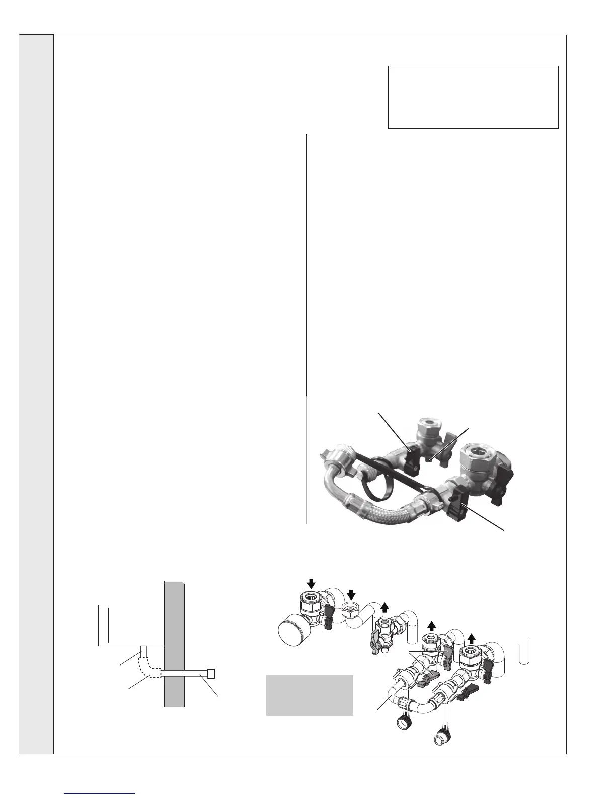
Handle

Handle

Nipple drain point for
recuperator (if required)
IMpORTaNT -whenlling:


1. 
2. Ensure dust cap on auto air vent is slackened off (refer to

3. Check all isolation handles on all water connections are in

4. Open handle 

5. 

6. 

7. 

FILLINg


NOTEs.
Ensure all boss blanking plugs are removed before connecting hardware. Each
valve must be tted to the correct boss as shown in the picture.
Ensure each union is tted with bre seals provided.
Do not subject any of the isolating valves to heat as the seals may be damaged.
WaTER CONNECTIONs Ch
1. 
copper tail provided in the hardware pack to the threaded

2. 
3. If connecting the boiler to heating loads in excess of




gas CONNECTION
IMpORTaNT. 
       



saFETy V aLVE DRaIN



of water or steam cannot create a hazard to the occupants of

WaTER CONNECTIONs DhW
1. Fit the DHW inlet service valve (blue handle) and copper tail
to the threaded boss connection ensuring the seal provided

2. Fit the DHW outlet pipe tail to DHW outlet connection,

3. 
the CH return valve
INsTaLLa TION
Note that all isolation
handles are shown in
the open postion.
3G9705
Safety Valve
Drain Connection
15mm elbow
or fittings
(not supplied)
Safety Valve
Drain Pipe

Other manuals for IDEAL Logic Code Combi ES26

Related product manuals