26
INTERNaL WIRINg
a permanent call for heat and must be removed when adding a room
1.
2.
3.
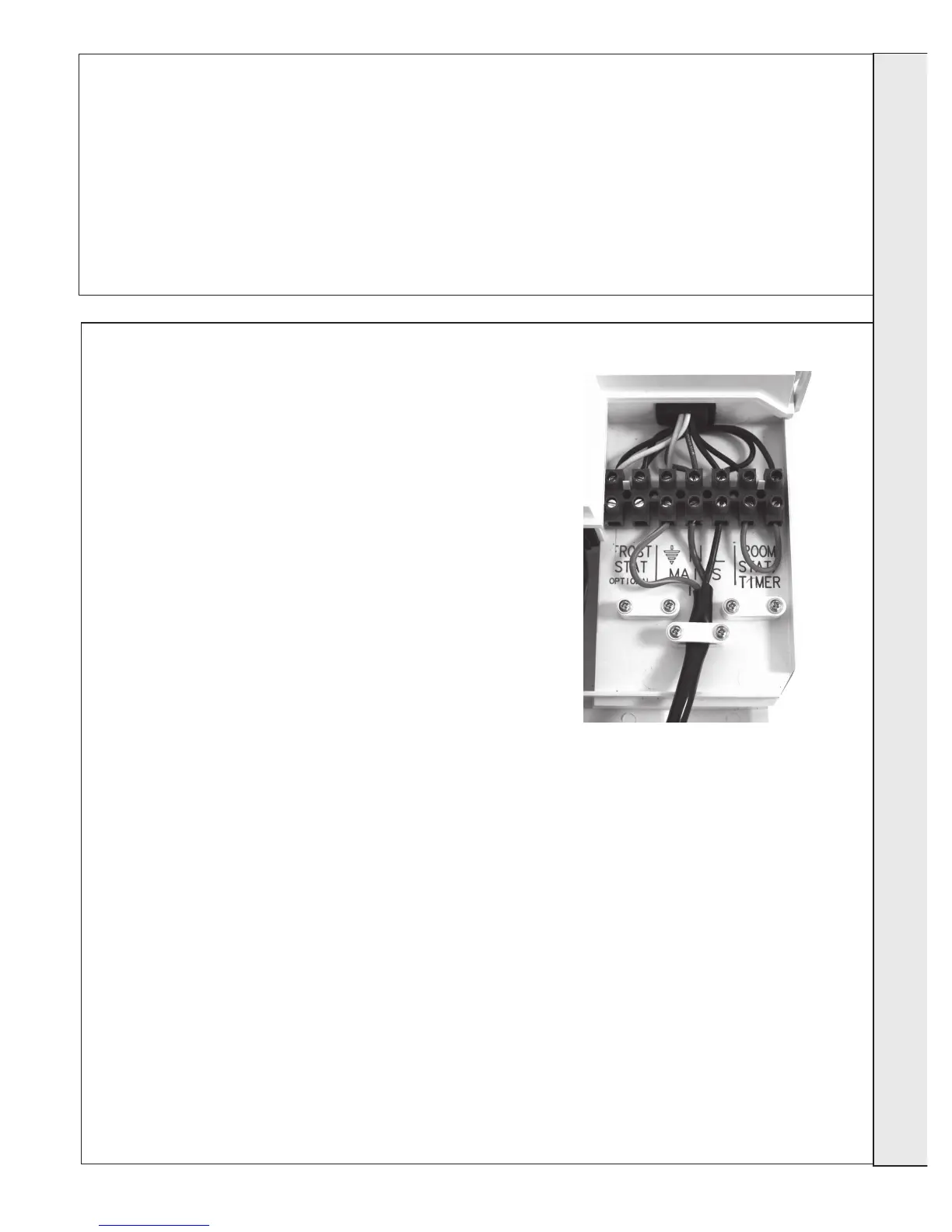
4. Route incoming cables through the grommets in bottom panel (note,
5.
6.
Ideal offer 4 kits as follows:
(see individual kits for installation instructions)
Mechanical Timer (24 hr) Kit - 24 hour mechanical CH
Electronic Timer (7 day) kit - 7 day electronic CH timer
RF Mechanical programmable Room Thermostat (24
hr) kit - Combined 24 hour mechanical timer and room
thermostat with wireless communication to receiver unit
RF Electronic programmable Room Thermostat (7
day) kit - Combined 7 day timer and room thermostat
ROOM ThERMOsTaT (NO TIMER) - WIRINg
1.
2. Connect room stat across terminals as shown in diagram A -
3. If room stat has a neutral connection, connect this to terminal
ROOM ThERMOsTaT + TIMER - WIRINg
1.
2. Connect room stat and programmer in series as shown in
3. If room stat has a neutral connection, connect this to terminal
FROsT ThERMOsT aT - WIRINg
If parts of the system are vulnerable to freezing or the
programmer is likely to be left off during cold weather, a frost stat
1.
2. Connect frost stat across terminals marked frost stat as
25
ELECTRICaL CONNECTIONs
2
Connection must be made in a way that allows complete
isolation of the electrical supply such as a double pole switch
means of isolation must be accessible to the user after
Warning
INsTaLLa TION