EasyManua.ls Logo

IDEAL Logic Code Combi ES26

IDEAL Logic Code Combi ES26
66 pages
To Next Page IconTo Next Page
To Previous Page IconTo Previous Page
Loading...

sERVICINg
Ideal Logic Code Combi ES - Installation and Servicing
68
hEa T ENgINE RENEWaL
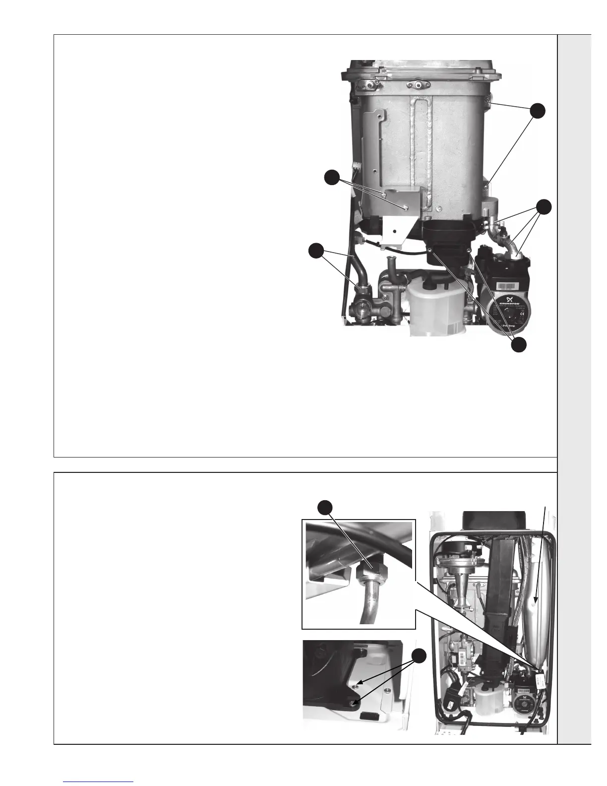
Refer also to Frame 6 - ‘Boiler Exploded View’
IMpORTaNT
Before starting the removal procedure, protect the gas and

1. 
2. 
3. 

4. 

5.

6. Remove the ignition and detection electrodes and divertor

7. 
8. 
9. 

10. 
11. Remove the 2 M5 screws retaining the gas valve mounting

12.
13. Undo the return pipe union nut and remove the retaining

14. Unclip and disconnect the DHW pipe off the brass inlet

15. 
16.

17. 
18. Remove the Heat exchanger, slide to the right out of location

19. Reassemble in reverse order, ensuring the heat exchanger



17
13
15
11
When replacing the spring clips located on the return
pipe connection, ensure clip is oriented to correctly match

20. 
21. 
22.
69
ExpaNsION VEssEL REChaRgINg & REpLaCEMENT
10
REChaRgINg
1. 
2. Relieve system pressure through CH drain point (Refer to

3. 
4. 
5. Re-assemble in reverse order
6.


REpLaCEMENT
7. 
8. 
9.

10.

from the securing clamp, located on the top of the boiler, and

11. 
12.
13.
14. 
15.


3
sERVICINg

Other manuals for IDEAL Logic Code Combi ES26

Related product manuals