2: P
RODUCT
S
PECIFICATIONS
2-116 FC6A S
ERIES
MICROS
MART
U
SER
’
S
M
ANUAL
FC9Y-B1722
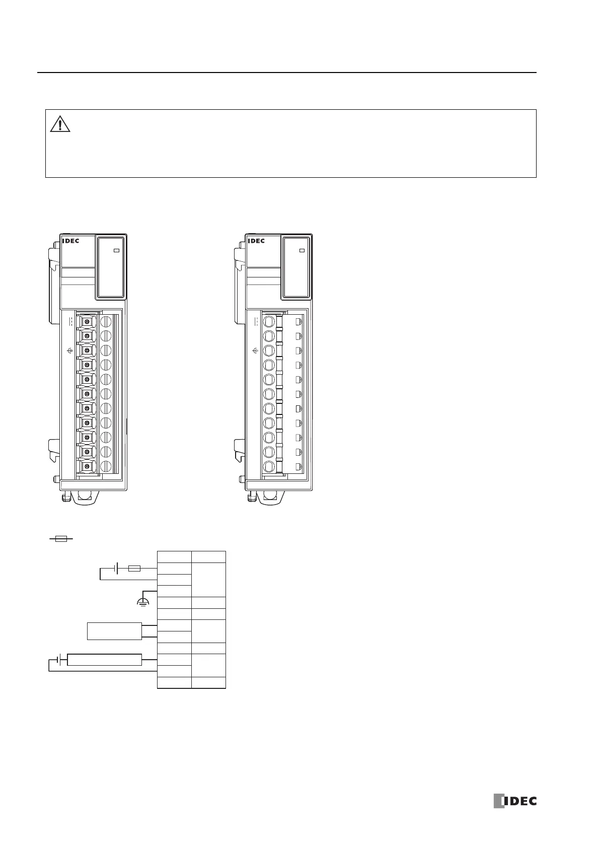
Terminal Arrangement and Wiring Examples
■ FC6A-J2C1, FC6A-J2C4
For wiring precautions, see "Input/Output Wiring" on page 3-18.
*1 24V DC for products with a version number lower than V400. For details on the version number of modules, see "Checking the Version Number"
on page 2-1.
When connecting the terminal, insert an IEC 60127-approved fuse suitable for the applied voltage and current draw at
the position shown in the following diagram.
(Applicable when equipment containing the FC6A Series MICROSmart is destined for Europe)
Do not connect a thermocouple to a part with hazardous voltage (60V DC or peak 42.4V DC or higher part).
Before turning on the power, always check the wiring. If wiring is incorrect, the analog I/O module may be damaged.
Caution
Screw fastened type: FC6A-J2C1 Push-in type: FC6A-J2C4
Applicable connector: FC6A-PMTB11PN02 Applicable connector: FC6A-PMSB11PN02
PWR
ANALOG
FC6A-J2C1
NC I1- I1+ NC I0- I0+ NC NC 0V
24V
PWR
ANALOG
FC6A-J2C4
NC I1- I1+ NC I0- I0+ NC NC 0V
24V
0V
24V
Terminal No.
I/O
FE
NC
I1+
I1-
NC
NC
I0+
I0-
NC
12/24V
DC
*1
NC
NC
NC
IN0
IN1
NC
-
+
+
-
Analog Voltage/
current Output Device
2-wire Analog Output Sensor
-
+

 Loading...