FC6A S
ERIES
MICROS
MART
U
SER
’
S
M
ANUAL
FC9Y-B1722 5-37
5: F
UNCTIONS
AND
S
ETTINGS
Interrupt Input
When a quick response to an external input is required, such as positioning control, the interrupt input can call a subroutine to
execute an interrupt program.
Six inputs I0, I1, I3, I4, I6, and I7 can be designated to execute interrupt at a rising and/or falling edge of input pulses. When an
interrupt is initiated by inputs I0, I1, I3, I4, I6 and I7, program execution immediately jumps to a predetermined label number
stored in special data registers D8215, D8032 through D8035, and D8214 respectively. The Function Area Settings dialog box is
used to designate inputs I0, I1, I3, I4, I6 and I7 as an interrupt input, normal input, high-speed counter input, or catch input.
Normal input signals to input terminals are read when the END instruction is executed at the end of a scan.
Since these settings relate to the user program, the user program must be downloaded to the FC6A Series MICROSmart after
changing any of these settings.
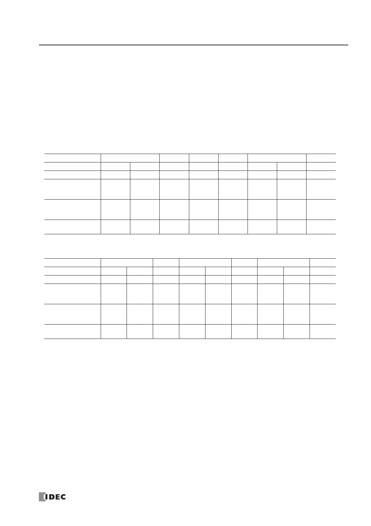
Interrupt Input Terminals, Special Data Registers, and Special Internal Relays for Interrupt Inputs
All-in-One CPU module
*1 Can be used as a normal input.
Plus CPU module
*1 Can be used as a normal input.
*2 Can be used only with the Plus 32-I/O type.
Group 123456
External Input I2 I0 I1 I3 I4 I5 I6 I7
Interrupt Input —
*1
Yes Yes Yes Yes —
*1
Yes Yes
Special Data Register
(Jump Destination
Label No.)
— D8215 D8032 D8033 D8034 — D8035 D8214
Special Internal Relay
(Interrupt Input
Status)
— M8137 M8140 M8141 M8142 — M8143 M8167
Special Internal Relay
(Interrupt Input Edge)
M8192 M8197 M8193 M8194 — M8195 M8196
Group 123456
External Input I2 I0 I1 I13
*2
I3 I4 I5 I6 I7
Interrupt Input —
*1
Yes Yes —
*1
Yes Yes —
*1
Yes Yes
Special Data Register
(Jump Destination
Label No.)
— D8215 D8032 — D8033 D8034 — D8035 D8214
Special Internal Relay
(Interrupt Input
Status)
— M8137 M8140 — M8141 M8142 — M8143 M8167
Special Internal Relay
(Interrupt Input Edge)
— M8192 M8197 — M8193 M8194 — M8195 M8196

 Loading...