5: F
UNCTIONS
AND
S
ETTINGS
5-38 FC6A S
ERIES
MICROS
MART
U
SER
’
S
M
ANUAL
FC9Y-B1722
Programming WindLDR
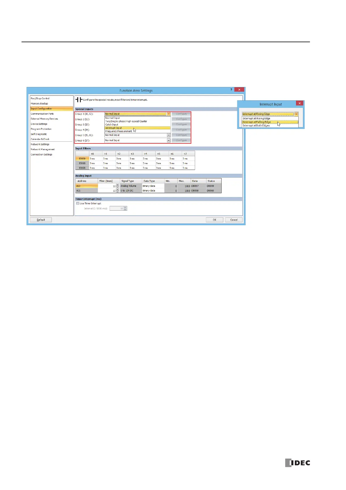
1. From the WindLDR menu bar, select Configuration > Input Configuration.
The Function Area Settings dialog box for Input Configuration appears.
2. Select Interrupt Input in the Groups 1 through 6 pull-down list boxes. the Interrupt Input dialog box appears.
3. Select an interrupt edge in the pull-down list for each group.
Disable and Enable Interrupts
The interrupt inputs I0, I1, I3, I4, I6, and I7 and timer interrupt are normally enabled while the FC6A Series MICROSmart is
running, and can also be individually disabled using the DI instruction or enabled using the EI instruction. When interrupt inputs
I0, I1, I3, I4, I6, and I7 are enabled, special internal relay M8137 through M8143, and M8167 are turned on, respectively. See
Chapter 14 "Refresh Instructions" in the "FC6A Series MICROSmart Ladder Programming Manual".
Interrupt Input Rising/
Falling Edge Selection
Interrupt at Rising Edge
Interrupt occurs when the
interrupt input turns on.
Interrupt at Falling Edge
Interrupt occurs when the
interrupt input turns off.
Interrupt at Both Edges
Interrupt occurs when the
interrupt input turns on or off.

 Loading...