FC6A S
ERIES
MICROS
MART
U
SER
’
S
M
ANUAL
FC9Y-B1722 9-1
9: ANALOG I/O MODULES
This chapter describes the configuration of the analog I/O modules, as well as their parameters, device allocations, and WindLDR
configuration methods.
Analog I/O Module Overview
This section provides an overview of the analog I/O modules and describes their types and the maximum number of modules that
can be connected to the CPU module.
Analog I/O modules are available that allow the FC6A Series MICROSmart to directly handle analog data such as voltage, current,
and temperature. There are ten types of analog I/O modules that differ by the number of analog inputs and outputs and the
operation mode. These analog I/O modules can be used by connecting them to the right side of the CPU module. Analog I/O
module inputs support voltage, current, thermocouples, resistance thermometers, and thermistors. Analog I/O module outputs
support voltage and current.
To use an analog I/O module, it must be configured in the Module Configuration Editor. For detailed configuration methods, see
"Module Configuration Editor" on page 12-1. For details on the analog I/O module parameter settings, see "Analog I/O Module
Parameter Settings" on page 9-4.
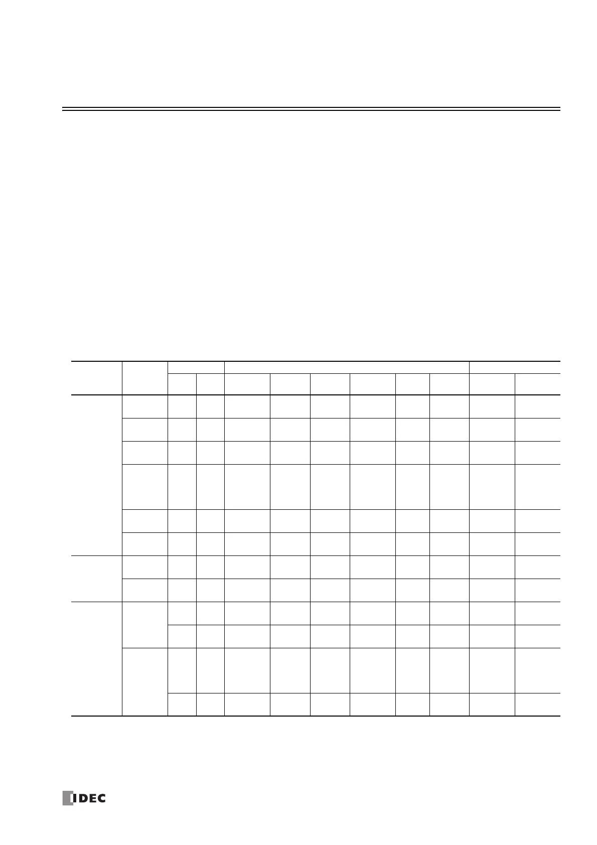
Analog I/O Module List
This section shows a list of the analog I/O modules.
Module
Type
Type No.
Points Input Type Output Type
Inputs
Outputs
Voltage Current
Thermocouple
Resistance
Thermometer
Thermistor
Resistance
measurement
Voltage Current
Analog input
module
FC6A-J2C1
FC6A-J2C4
2 ―
0 to 10 V/
-10 to +10 V
0 to 20 mA/
4 to 20 mA
――――― ―
FC6A-J4A1
FC6A-J4A4
4 ―
0 to 10 V/
-10 to +10 V
0 to 20 mA/
4 to 20 mA
――――― ―
FC6A-J8A1
FC6A-J8A4
8 ―
0 to 10 V/
-10 to +10 V
0 to 20 mA/
4 to 20 mA
――――― ―
FC6A-J4CN1
FC6A-J4CN4
4 ―
0 to 10 V/
-10 to +10 V
0 to 20 mA/
4 to 20 mA
K/ J/ R/ S/ B/
E/ T/ N/ C
Pt100/
Pt1000/
Ni100/
Ni1000/
―― ― ―
FC6A-J4CH1Y
FC6A-J4CH4Y
4 ―― ―
K/ J/ R/ S/ B/
E/ T/ N/ C
――― ― ―
FC6A-J8CU1
FC6A-J8CU4
8 ―― ―
K/ J/ R/ S/ B/
E/ T/ N/ C
― NTC/PTC
100 to
10,000 Ω
――
Analog output
module
FC6A-K2A1
FC6A-K2A4
― 2 ――――――
0 to 10V/
-10 to +10V
0 to 20mA/
4 to 20mA
FC6A-K4A1
FC6A-K4A4
― 4 ――――――
0 to 10 V/
-10 to +10 V
0 to 20 mA/
4 to 20 mA
Mixed analog
I/O module
FC6A-L06A1
FC6A-L06A4
4 ―
0 to 10 V/
-10 to +10 V
0 to 20 mA/
4 to 20 mA
――――― ―
― 2 ――――――
0 to 10 V/
-10 to +10 V
0 to 20 mA/
4 to 20 mA
FC6A-L03CN1
FC6A-L03CN4
2 ―
0 to 10 V/
-10 to +10 V
0 to 20 mA/
4 to 20 mA
K/ J/ R/ S/ B/
E/ T/ N/ C
Pt100/
Pt1000/
Ni100/
Ni1000/
―― ― ―
― 1 ――――――
0 to 10 V/
-10 to +10 V
0 to 20 mA/
4 to 20 mA

 Loading...