2: P
RODUCT
S
PECIFICATIONS
2-148 FC6A S
ERIES
MICROS
MART
U
SER
’
S
M
ANUAL
FC9Y-B1722
(4) ACT LED [ACT]
This LED flashes when the module is communicating with the expansion interface remote slave module connected using an
Ethernet cable.
(5) Expansion Connector 1
This connector is used to connect the Plus CPU module or an expansion module.
(6) Expansion Connector 2
This connector is used to connect an expansion module.
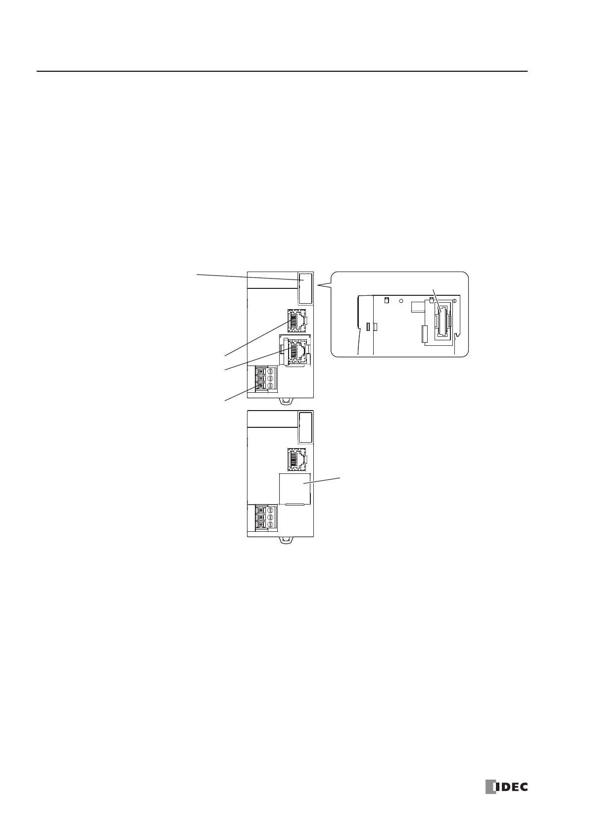
(7) Expansion Port [Exp. port M]
This port is used to connect an expansion interface remote slave module using an Ethernet cable.
(8) Ground Terminal
The functional ground terminal.
■ Expansion Interface Remote Slave Module
(1) Power LED [PWR]
This LED turns on when the power is supplied to the expansion interface remote slave module.
(2) Run LED [RUN]
This LED turns on when the expansion interface remote slave module is operating.
(3) Error LED [ERR]
This LED turns on when the following errors occur in the expansion interface remote slave module.
When the cable breaks (data is not normally received for 10 seconds or longer on expansion port 1 [Exp. port S1])
When the following occur for a connected expansion module:
(4) LINK1 LED [LNK]
This LED turns on when the expansion interface remote master module or upstream expansion interface remote slave
module is connected to expansion port 1 [Exp. port S1] using an Ethernet cable.
An unsupported module was connected.
Exceeded 15 modules.
Exceeded seven modules on the basic expansion side.
Exceeded eight modules on the expansion interface side.
Initialization error
(11) Power Supply Terminals
(12) Expansion Port 2 [Exp. port S2] Cover
(10) Expansion Port 2 [Exp. port S2]
(9) Expansion Port 1 [Exp. port S1]
(1) Power LED [PWR]
(2) Run LED [RUN]
(3) Error LED [ERR]
(4) LINK1 LED [LNK]
(5) ACT1 LED [ACT]
(6) LINK2 LED [LNK]
(7) ACT2 LED [ACT]
(8) Expansion Connector

 Loading...