FC6A S
ERIES
MICROS
MART
U
SER
’
S
M
ANUAL
FC9Y-B1722 3-5
3: I
NSTALLATION
AND
W
IRING
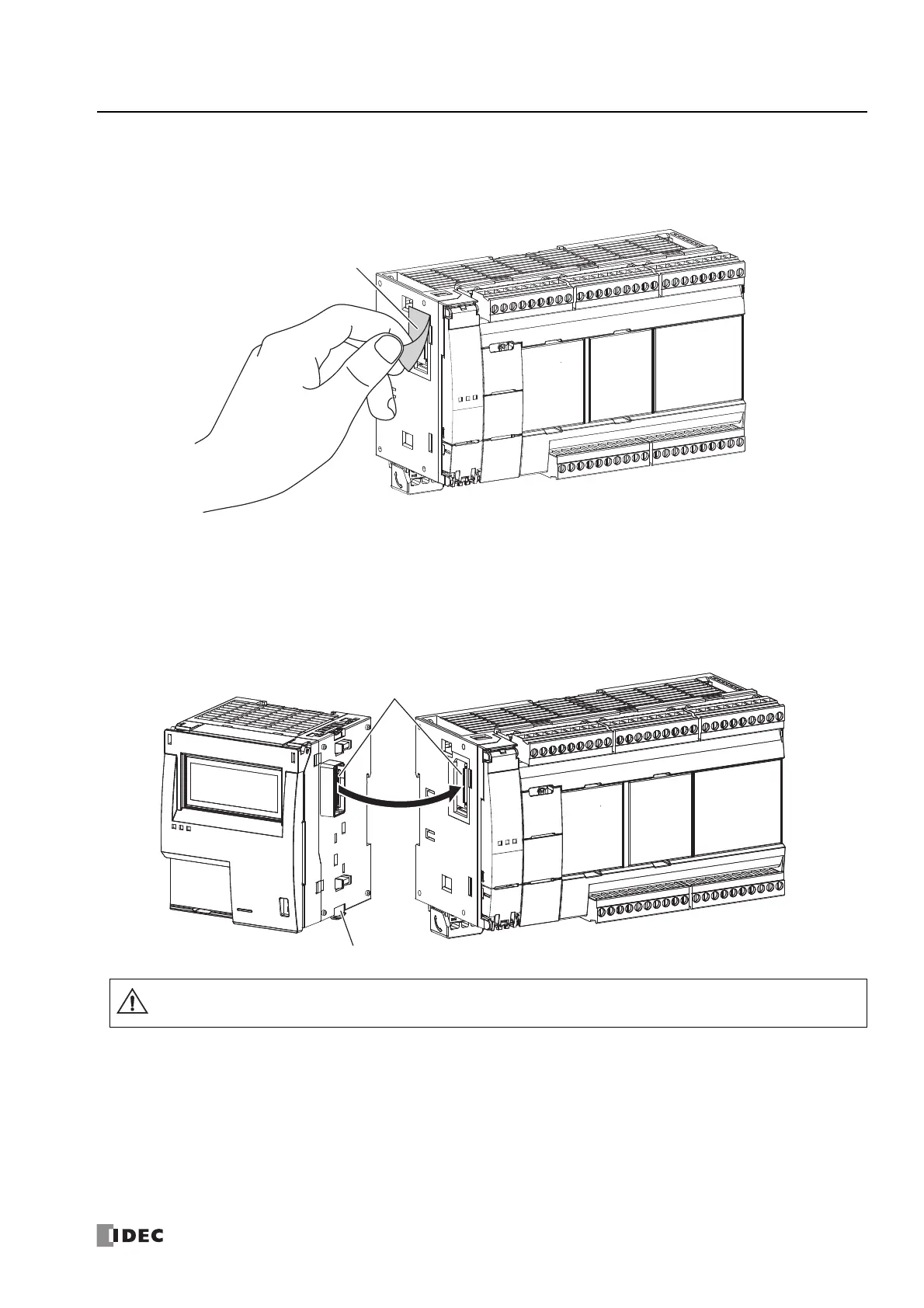
Assembling the CPU Module and the HMI Module
The following procedure describes the assembly of the CPU module and the HMI module.
1. Peel off the protection sticker applied to the communication connector on the CPU module.
2. Line up the HMI module alongside the CPU module.
Note: The CPU module and the HMI module are easier to line up if you use the position of the communication connector as a guide.
3. Confirm that the HMI module eject button is depressed and push the HMI module until it clicks while taking care with the
position of the communication connector. If the eject button is not depressed, push in the eject button until it clicks after the
HMI module has been pushed onto the CPU module.
The HMI module is now locked on the CPU module.
Communication Connector Protection Sticker
Eject Button
Communication Connector
Do not perform this work when the FC6A Series MICROSmart is powered. Otherwise there is a risk of damage.

 Loading...