3: I
NSTALLATION
AND
W
IRING
3-12 FC6A S
ERIES
MICROS
MART
U
SER
’
S
M
ANUAL
FC9Y-B1722
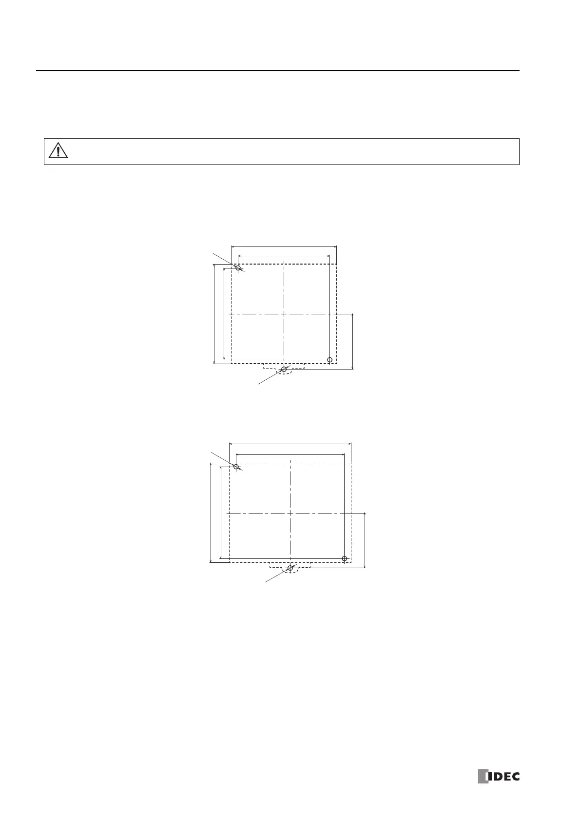
Mounting Hole Layout for Direct Mounting on Panel Surface
As shown in the following diagram, mount the FC6A Series MICROSmart to the mounting plate with M4 pan head screws.
Always give sufficient consideration to operability, ease-of-maintenance, and environmental resistance when deciding on the
mounting position.
■ CPU Modules
When directly mounting the FC6A Series MICROSmart, tighten mounting screws with torque of 1 N·m (kgf·cm).
Caution
16-I/O type:
Screw fastened type: FC6A-C16R1AE, FC6A-C16R1CE, FC6A-C16K1CE, FC6A-C16P1CE,
FC6A-C16R1DE, FC6A-C16K1DE, FC6A-D16P1DE
Push-in type: FC6A-C16R4AE, FC6A-C16R4CE, FC6A-C16K4CE, FC6A-C16P4CE,
FC6A-C16R4DE, FC6A-C16K4DE, FC6A-D16P4DE
24-I/O type:
Screw fastened type: FC6A-C24R1AE, FC6A-C24R1CE, FC6A-C24K1CE, FC6A-C24P1CE
Push-in type: FC6A-C24R4AE, FC6A-C24R4CE, FC6A-C24K4CE, FC6A-C24P4CE
Ø
4.5
2-
Ø
4.3
90.0
95.0
83.0
±0.2
83.0
±0.2
50.0
±0.2
50.0
±0.2
110.0
98.0
±0.2
Ø
4.5
2-
Ø
4.3
90.0
83.0
±0.2

 Loading...