FC6A S
ERIES
MICROS
MART
U
SER
’
S
M
ANUAL
FC9Y-B1722 3-21
3: I
NSTALLATION
AND
W
IRING
■ Inrush Current at Powerup
The following inrush current flows through the FC6A Series MICROSmart when powered up. Use a power supply with sufficient
capacity.
AC power type: 40 A or lower
24V DC power type: 35 A or lower
12V DC power type: 35 A or lower
Expansion interface module
The power supply specification of the expansion interface module (expander) and expansion interface remote slave module is the
24V DC power type.
■ Power Supply Voltage
The power supply voltage that can be used with the expansion interface module (expander) and expansion interface remote
slave module is 20.4 to 28.8V DC.
The power failure detection voltage varies depending on the usage conditions of the inputs and outputs, but a power failure is
normally detected when the power supply voltage is less than 20.4V DC.
A momentary power interruption of 10 ms or less is not recognized as a power failure when the power voltage is at the rated voltage.
■ Inrush Current at Powerup
An inrush current of 35 A or lower flows through the expansion interface module (expander) and expansion interface remote slave
module when powered on. Use a power supply with sufficient capacity.
About the sequence to turn on and off the I/O power supply
When automatically running and stopping the FC6A Series MICROSmart in conjunction with turning the power supply to the FC6A
Series MICROSmart on and off, use the following sequence to turn on and off the I/O power supply and CPU module main power
supply. If the sequence is wrong, inputs and outputs may be mistakenly activated.
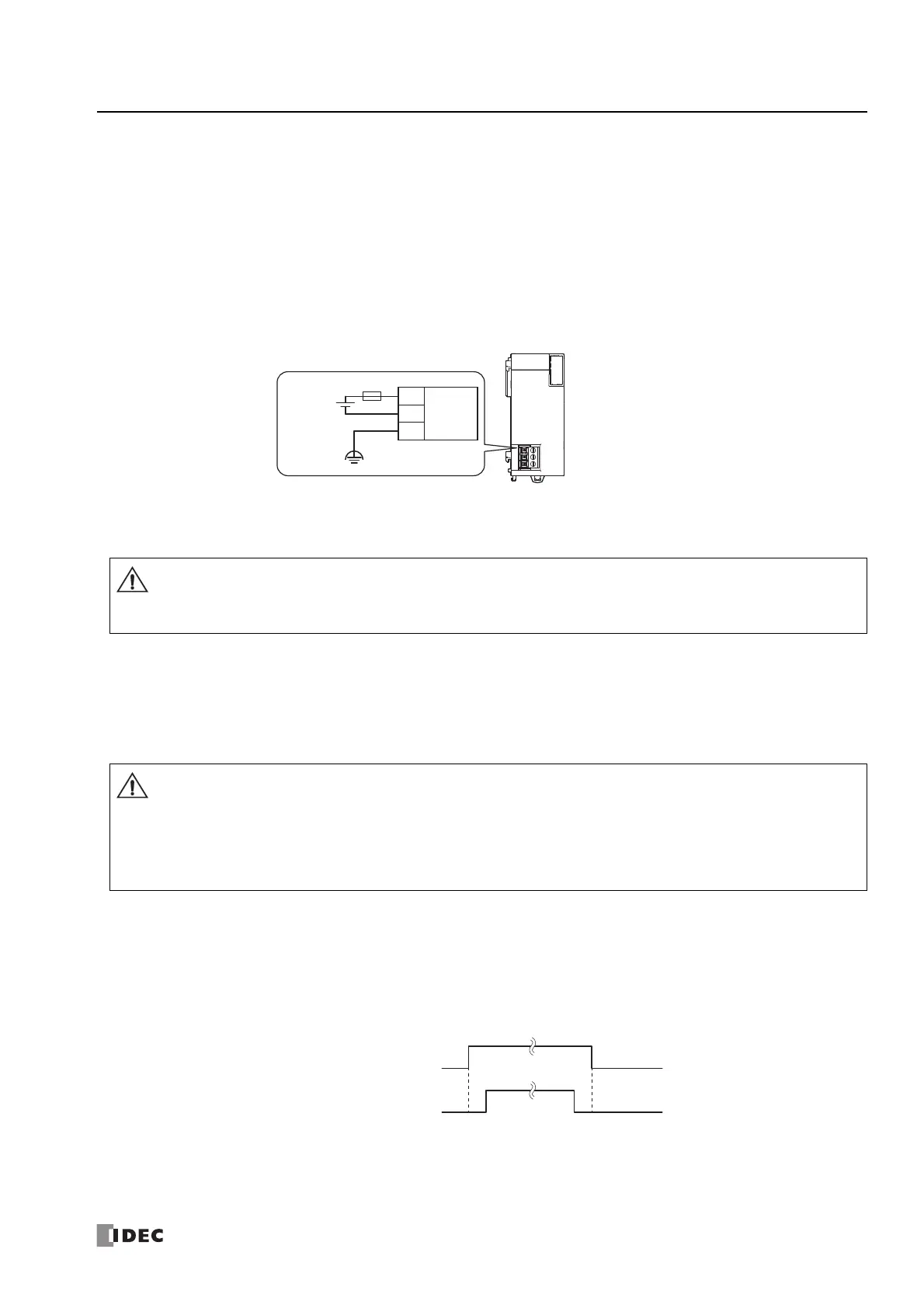
Expansion Interface Module (Expander)
-
+
External
Power Supply
24V DC
24V DC
Power Input
+
-
FE
Do not use the FC6A Series MICROSmart outside of the power supply voltages listed above.
When using the expansion interface module and an external device that carries the risk of causing a serious accident has
been connected, implement measures in the external circuit (such as voltage monitoring) so that the device will function
safely when there is a failure.
When using the CPU module, expansion interface module (expander), and expansion interface remote slave module with
separate power supplies, turn the power on and off in the following order.
Power-up: Expansion interface module (expander) -> Expansion interface remote slave module (Downstream -> Upstream)
-> CPU module
Power-down: CPU module -> Expansion interface remote slave module (Upstream -> Downstream) -> Expansion interface
module (expander)
If the power supply is not shut off with the above sequence, the I/O for all expansion modules will not be updated.
Power on: I/O power supply → CPU module main power
Power off: CPU module main power → I/O power supply
I/O power supply
CPU module main power
ON
OFF
ON
OFF

 Loading...