FC6A S
ERIES
MICROS
MART
U
SER
’
S
M
ANUAL
FC9Y-B1722 5-47
5: F
UNCTIONS
AND
S
ETTINGS
Programming WindLDR
To use the analog potentiometer, you must configure the Function Area Settings in WindLDR and download the user program to
the FC6A Series MICROSmart.
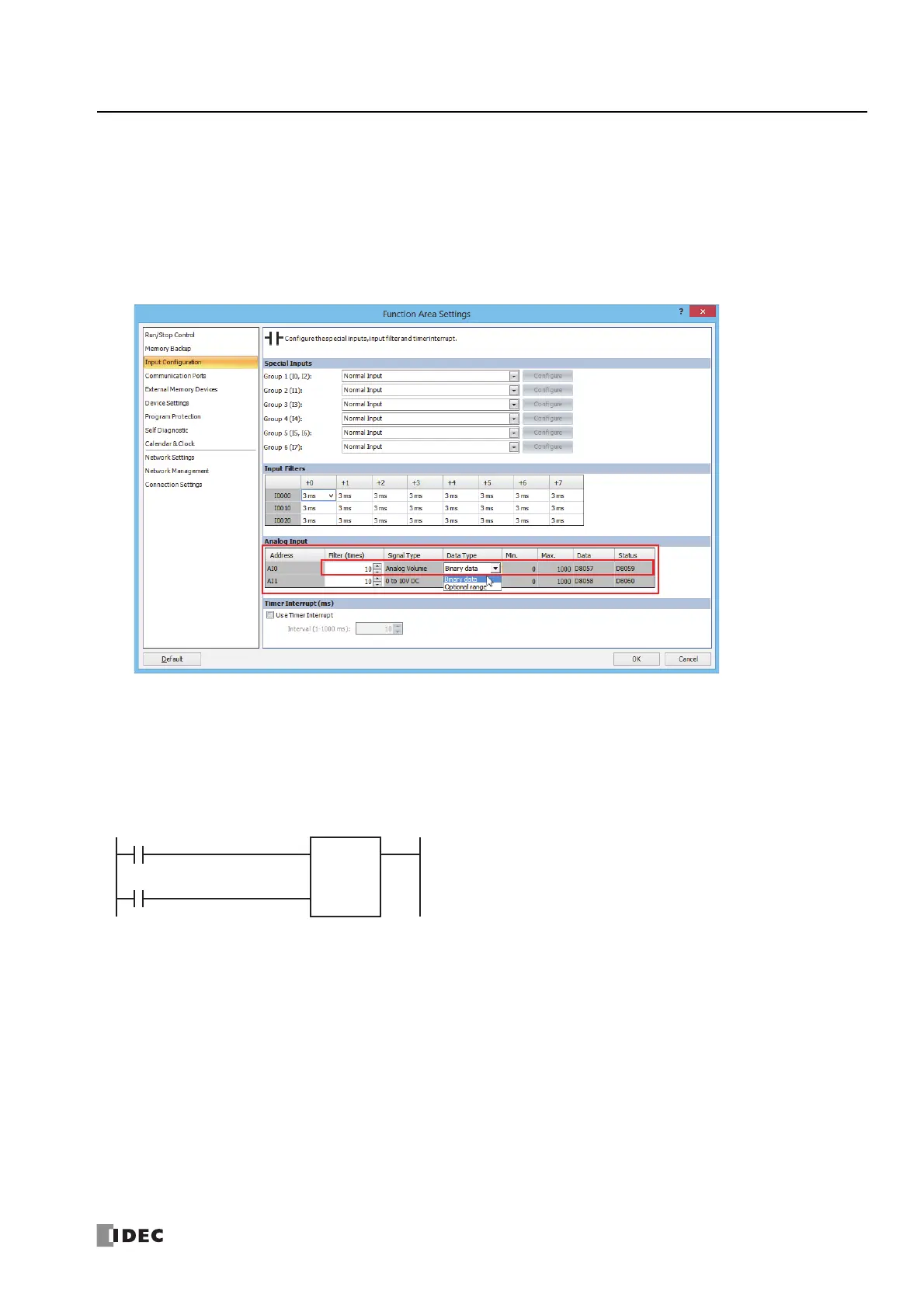
1. On the Configuration tab, in the Function Area Settings group, click Input Configuration.
The Function Area Settings dialog box is displayed.
2. For AI0, configure the filter count and data type for the analog Potentiometer.
The AI0 signal type is fixed as "Analog Potentiometer".
3. Click OK.
This concludes configuring the settings.
Example program
This program uses the analog potentiometer value for the counter preset value.
When reset input M0000 turns on, the current value is reset to "0".
While reset input M0000 is off, the counter can count.
While the counter is in the state where it can count, it increments +1
with each rise in up clock input M0001.
When the current value reaches analog potentiometer value D8057,
counting ends, and the counter output is maintained until reset input
M0000 is turned on.
M0000
M0001
Reset Input
Up clock input
CNT C000
D8057

 Loading...