FC6A S
ERIES
MICROS
MART
U
SER
’
S
M
ANUAL
FC9Y-B1722 5-49
5: F
UNCTIONS
AND
S
ETTINGS
Disable and Enable Interrupts
The timer interrupt and interrupt inputs I0, I1, I3, I4, I6 and I7 are normally enabled while the FC6A Series MICROSmart is
running, and can also be individually disabled using the DI instruction or enabled using the EI instruction. When timer interrupt is
enabled, M8144 is turned on. When disabled, M8144 is turned off. See Chapter 15 "Interrupt Control Instructions" in the "FC6A
Series MICROSmart Ladder Programming Manual".
Example: Timer Interrupt
The following example demonstrates a program of using the timer interrupt function. The Function Area Settings must also be
completed to use the timer interrupt function as described on the preceding page.
Notes for Using Timer Interrupt and Interrupt Inputs:
When using a timer interrupt or interrupt input, separate the interrupt program from the main program using the END instruction at the end
of the main program.
When an interrupt program calls another subroutine, a maximum of 3 subroutine calls can be nested. If more than 3 calls are nested, a user
program execution error occurs, turning on special internal relay M8004 and the ERR LED.
When using a timer interrupt or interrupt input, include the label number of the interrupt program to be executed when an interrupt occurs.
The label numbers stored in data registers D8214, D8215, D8032 through D8035 specify the interrupt programs for interrupt inputs I0, I1, I3,
I4, I6 and I7 and timer interrupt, respectively.
If an interrupt is initiated while another interrupt program is executed, the subsequent interrupt program is executed after the prior interrupt
is completed. Multiple interrupt programs cannot be executed simultaneously.
Make sure that the execution time of the interrupt program is shorter than interrupt intervals sufficiently.
Interrupt programs cannot use the following instructions: SOTU, SOTD, TML, TIM, TMH, TMS, TMLO, TIMO, TMHO, TMSO, CNT, CDP, CUD,
CNTD, CDPD, CUDD, SFR, SFRN, WKTIM, WKTBL, WEEK, YEAR, MSG, DISP, DGRD, COMRF, DI, EI, XYFS, CVXTY, CVYTX, AVRG, PULS, PWM,
RAMP, ZRN, ARAMP, ABS, JOG, PID, PIDA, DTML, DTIM, DTMH, DTMS, TTIM, FIFOF, NDSRC, HOUR, SCALE, FLWA, FLWP, PING, EMAIL, TXD,
RXD, ETXD, ERXD, DLOG, TRACE, and SCRPT.
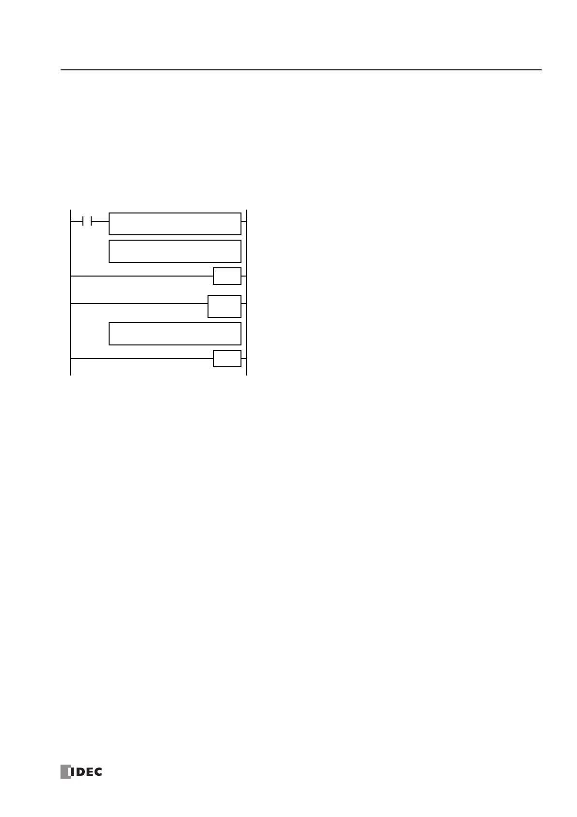
LABEL
0
M8120
END
Main Program
REPS1 –
0
D1 –
D8036
MOV(W)
LRET
Interrupt Program
M8120 is the initialize pulse special internal relay.
D8036 stores 0 to designate jump destination label 0 for timer interrupt.
The interrupt program is separated from the main program by the END instruction.
While the FC6A Series MICROSmart is running, program execution jumps to label 0
repeatedly at intervals selected in the Function Area Settings.
Each time the interrupt program is completed, program execution returns to the main
program at the address where timer interrupt occurred.
Insert LRET at the end of the subroutine to return to the main program.

 Loading...