FC6A S
ERIES
MICROS
MART
U
SER
’
S
M
ANUAL
FC9Y-B1722 5-65
5: F
UNCTIONS
AND
S
ETTINGS
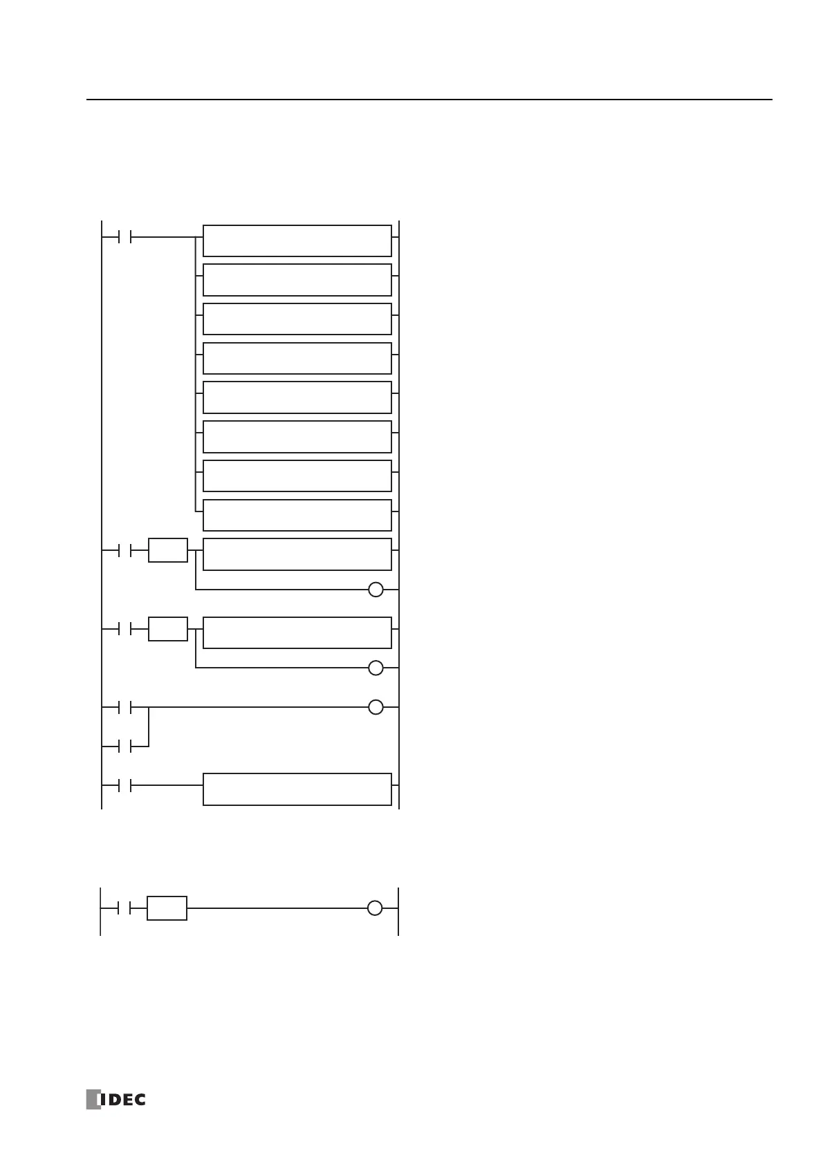
Example ladder program 1
This example sets the calendar and clock in a user program.
If you turn on M8020 with the new calendar/clock data set in the write-only data registers D8015 to D8021, the internal clock on
the FC6A Series MICROSmart is updated with the current time (calendar, clock). In this example, the FC6A Series MICROSmart
internal clock is set to 9:35:00 on Tuesday February 21, 2012.
Example ladder program 2
When I1 turns off to on, the seconds on the internal clock are corrected to 0 seconds.
When input I1 turns on, clock data adjust flag M8021 turns on to correct the seconds on the internal clock.
Note: The internal clock backup time is guaranteed for one year. If the backup time is exceeded, the retained clock data is lost and the current time
is initialized as 00:00:00 on January 1, 2000. For details on the battery, see "Battery Monitor" on page 5-66.
MOV(W) S1 R
D8008
D1 R
D8015
REP
7
M8120
MOV(W) S1
-
12
D1
-
D0000
REP
MOV(W) S1
-
2
D1
-
D0001
REP
MOV(W) S1
-
21
D1
-
D0002
REP
MOV(W) S1
-
2
D1
-
D0003
REP
MOV(W) S1
-
9
D1
-
D0004
REP
MOV(W) S1
-
35
D1
-
D0005
REP
MOV(W) S1
-
0
D1
-
D0006
REP
MOV(W) S1 R
D8000
D1 R
D8015
REP
4
I0000
M0000
SOTU
MOV(W) S1 R
D0004
D1 R
D8019
REP
3
I0001
M0001
SOTU
MOV(W) S1 R
D8008
D1 R
D0010
REP
7
M8125
M8020
M0000
M0001
M8120 is the initial pulse that turns on for only one scan at the start of
operation.
When the FC6A Series MICROSmart starts operating, the current calendar/
clock data is stored in D8015 to D8021 and the new calendar/clock data is
stored in D0 to D6 with the MOV (move) instruction.
When external input I0 turns on, the new calendar data is stored in special
data registers D8015 to D8018.
Internal relay M0 turns on for one scan only.
When external input I1 turns on, the new clock data is stored in special data
registers D8019 to D8021.
Internal relay M1 turns on for one scan only.
When external input M0 or M1 turns on, M8020 turns on and the calendar/
clock data is written to the internal clock.
(M8020: Calendar/Clock Data Write Flag)
M8125 is a special internal relay that is always on during operation.
While the FC6A Series MICROSmart is running, the current time (calendar,
clock) is stored in D10 to D16 with the MOV instruction.
M8021
I0001
SOTU

 Loading...