6: D
EVICES
6-40 FC6A S
ERIES
MICROS
MART
U
SER
’
S
M
ANUAL
FC9Y-B1722
■ D8268 to D8275, D8774 to D8781: Remote Host Number 1 to 255 (connection 1 to 16)
Special data registers that change the communications device when user communications client is set. For details, see Chapter 5
"Switching Remote Host Numbers" in the "FC6A Series MICROSmart Communication Manual".
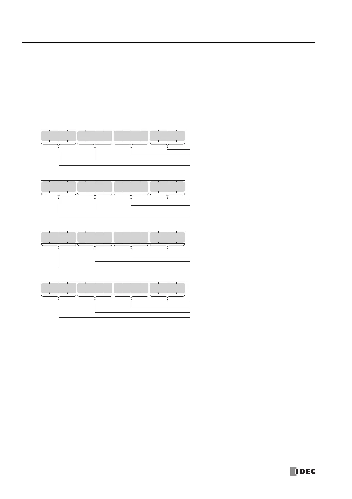
■ D8278, D8279, D8760, D8761: Communication Mode Information (Client Connection) (Connection 1 to 16)
D8278 = Indicates the communication mode of connections 1 through 4.
D8279 = Indicates the communication mode of connections 5 through 8.
D8760 = Indicates the communication mode of connections 9 through 12.
D8761 = Indicates the communication mode of connections 13 through 16.
The allocation of connections in the device (bit assignment) is as follows.
Client connection (most significant bit = 0)
0000: Unused
0001: User Communication
0010: Modbus TCP client
0100: User communication UDP
Server connection (most significant bit = 1)
1000: Maintenance Communication
1001: User Communication
1010: Modbus TCP server
Bit
15
Bit
0
Bit
7
Bit
8
Connection 1
Connection 2
Connection 3
Connection 4
D8278
Bit
15
Bit
0
Bit
7
Bit
8
Connection 5
Connection 6
Connection 7
Connection 8
D8279
Bit
15
Bit
0
Bit
7
Bit
8
Connection 9
Connection 10
Connection 11
Connection 12
D8760
Bit
15
Bit
0
Bit
7
Bit
8
Connection 13
Connection 14
Connection 15
Connection 16
D8761

 Loading...