12: M
ODULE
C
ONFIGURATION
E
DITOR
12-6 FC6A S
ERIES
MICROS
MART
U
SER
’
S
M
ANUAL
FC9Y-B1722
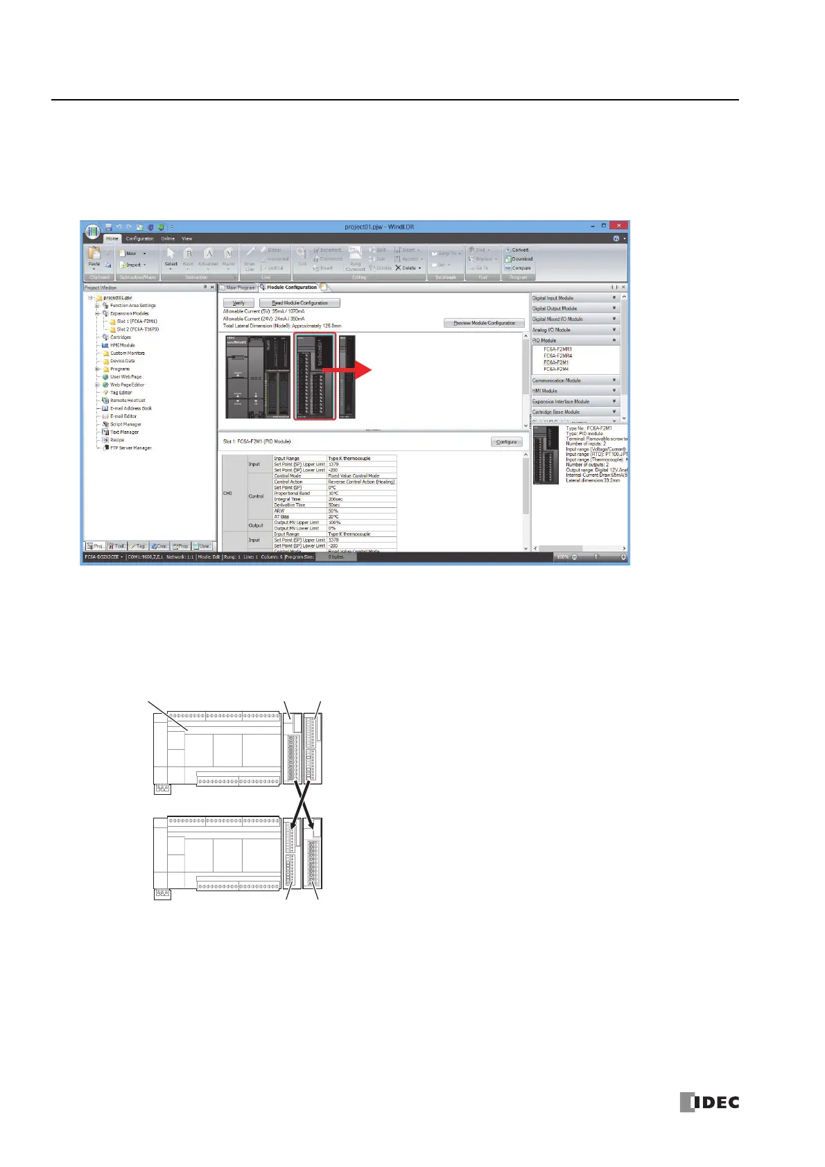
Swapping Expansion Modules and Cartridges
This section describes how to change the position of expansion modules and cartridges that have been inserted into the module
configuration area.
1. Select the expansion module or cartridge to move and drag and drop it onto the destination expansion module or cartridge.
Notes:
When the position of an I/O module is changed, the device addresses are automatically changed. For example, when the position of digital
input module (1) and (2) are changed as shown below, the device addresses I0030 to I0037 for digital input module (1) are changed to
I0050 to I0057. However, please note that the device addresses in the program are not replaced.
When the positions of an analog I/O module or analog I/O cartridge are changed, the configured parameters are also moved. However, the
device addresses in the program are not replaced.
CPU Module
Input Module (1)
Quantity of Inputs: 8
(I0030 to I0037)
Input Module (2)
Quantity of Inputs: 16
(I0040 to I0057)
Input Module (1)
Quantity of Inputs: 8
(I0050 to I0057)
Input Module (2)
Quantity of Inputs: 16
(I0030 to I0047)

 Loading...