Installation Procedures – Dipper Stick (Combo) Sensor
12
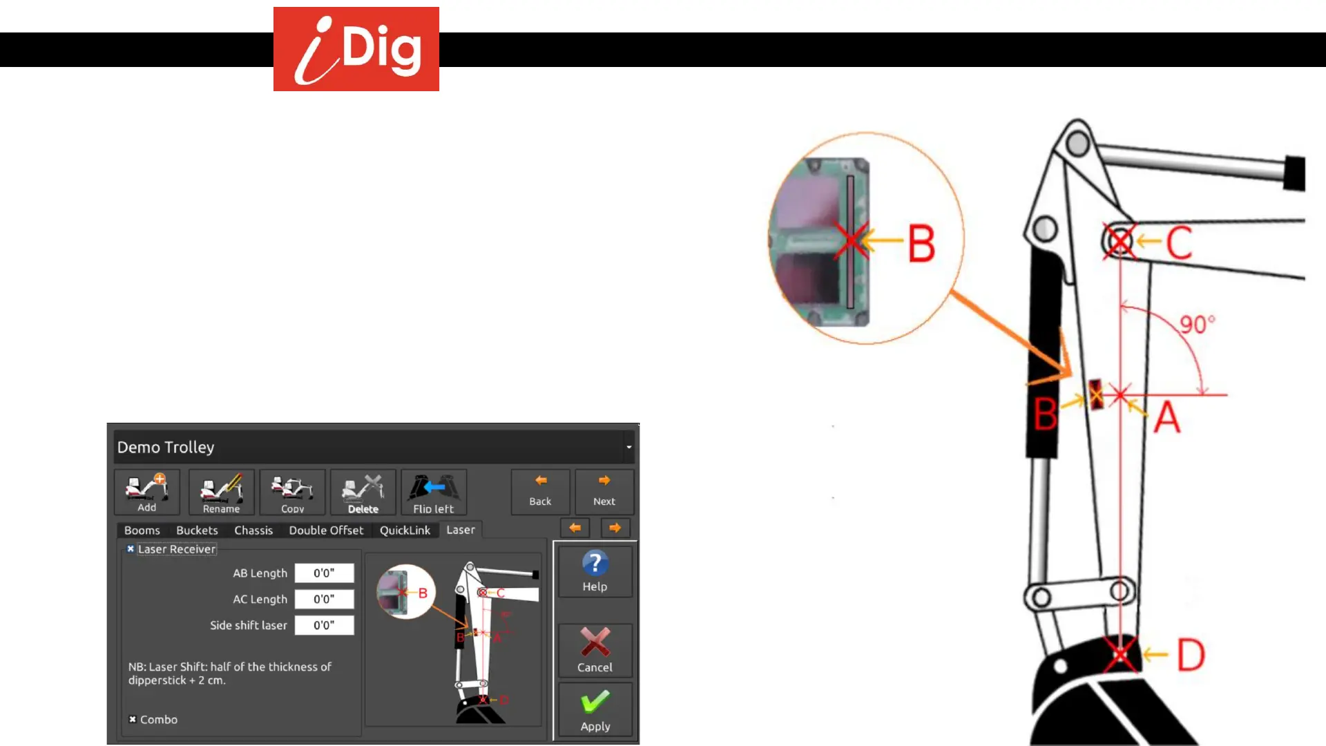
Recommended calibration of the Laser Receiver
• Using a magnetic plumb bob or a string and magnets, create a line
between the center points of the dipper stick/main boom pivot pin (C)
and the dipper stick/bucket pivot pin (D). (Line C-D)
• On the bottom 1/3 of the dipper stick place the Combo Sensor so that
the very center of the photo cell array (B) is on this line (C-D). Rotate the
sensor counter-clockwise slightly by 15° - 30°.
• Take a measurement from the center of the top pin (C) to the center of
the Combo Sensor (B) staying on the string line. This will be the A-C
measurement. The A-B measurement will be 0. Enter these
measurements via the System Settings menu once the main iDig
calibration steps have been completed.