IEI MiniMax 3 Installation/Programming Manual Section 2: Installation
2.7 Connect the Primary Wiegand Front End Reader (IN Reader)
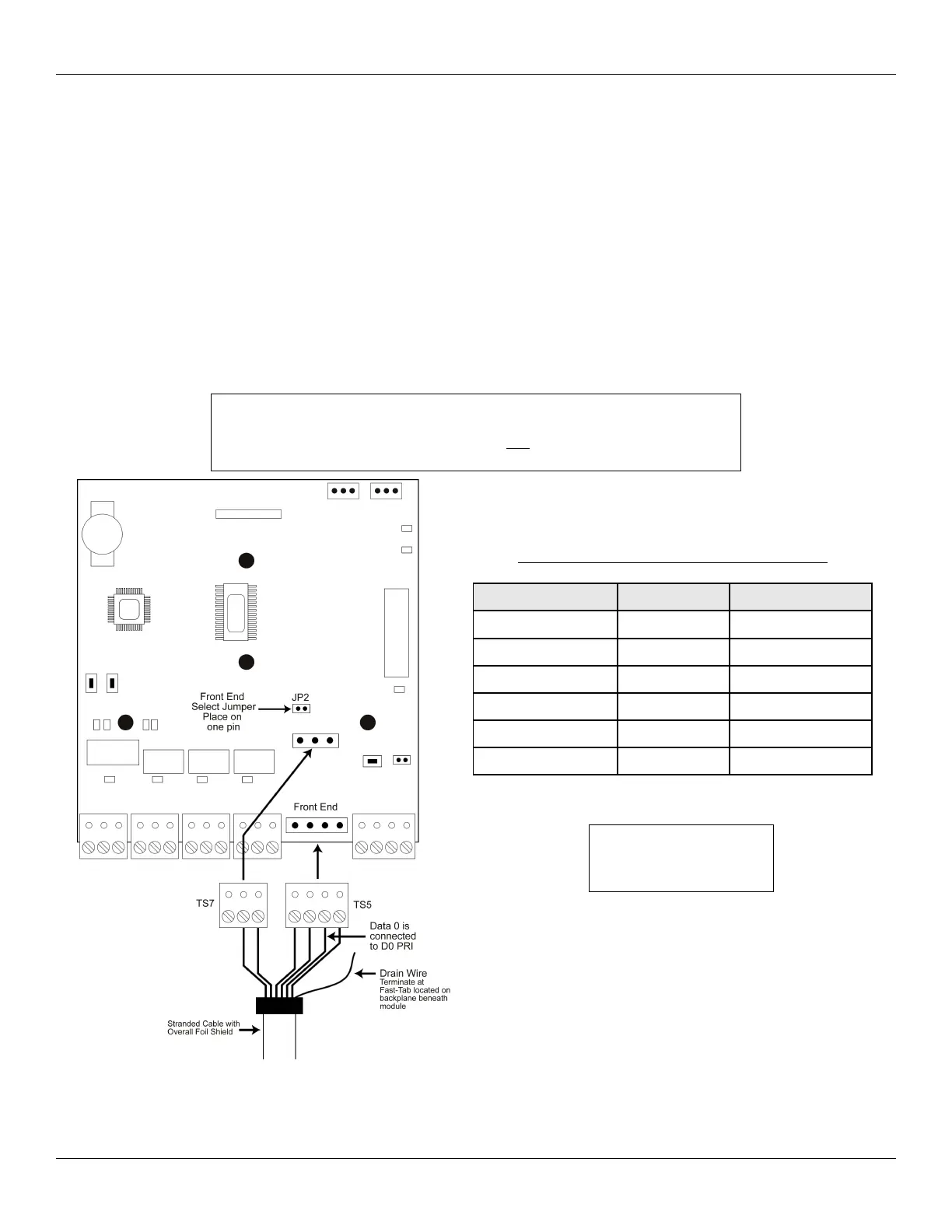
Wiegand readers are connected directly to the Front End Terminals on the Door Control Module. The primary reader (IN) should be
mounted on the exterior of the door and used to gain access into the secured area. The diagram and table below describe the
connections in detail. Please note that the Primary Wiegand Reader Data 0 wire is connected to DO PRI (Data 0 Primary) on terminal
strip TS5.
The LED connection is used to indicate status of the Main Relay and the Sounder connection is used to indicate various error
conditions. These are explained in more details in later sections.
You must use a four to six conductor stranded cable with overall foil shield to connect the Front End to the Door Control Module. You
also must terminate the drain wire (the bare wire inside the foil shield), from the front end cable, to the fast-tab located on the Max 3
Backplane. There is a fast-tab located under each module on the lower edge of the backplane. They are labeled FT1, FT2, FT3 and
FT4. Connect the drain wire from the front ends connected to module one to FT1 and so on. IEI has included four ground cables and
wire-nuts to make this connection. Do not terminate the drain wire at the Front End Reader. Cut off the exposed drain wire and
wrap the insulation and the foil shield in electrical tape.
Document #: 6055672, Rev 1.0 D1c Page 15 of 48
IMPORTANT: The Max 3 Door Control Module must be configured to
operate in Wiegand Front End Mode. To do this, locate jumper JP2 above
terminal strip TS7 and place the jumper on one pin. This is the default
condition.
Primary Wiegand Reader Connections
Wiegand Reader DCM Terminal Strip
V- (Power) Black TS5
V+ (Power) RED TS5
Data 0 D0 PRI TS5
Data 1 D1 TS5
LED Control LED TS7
Sounder Control SND TS7
Note: The primary reader
records an IN event in the
transaction log.
Figure 9: Connect Primary Wiegand Front End
Reader to DCM
 Loading...