Section 1: System Features and Specifications IEI MiniMax 3 Installation/Programming Manual
1.5 Backplane Diagram
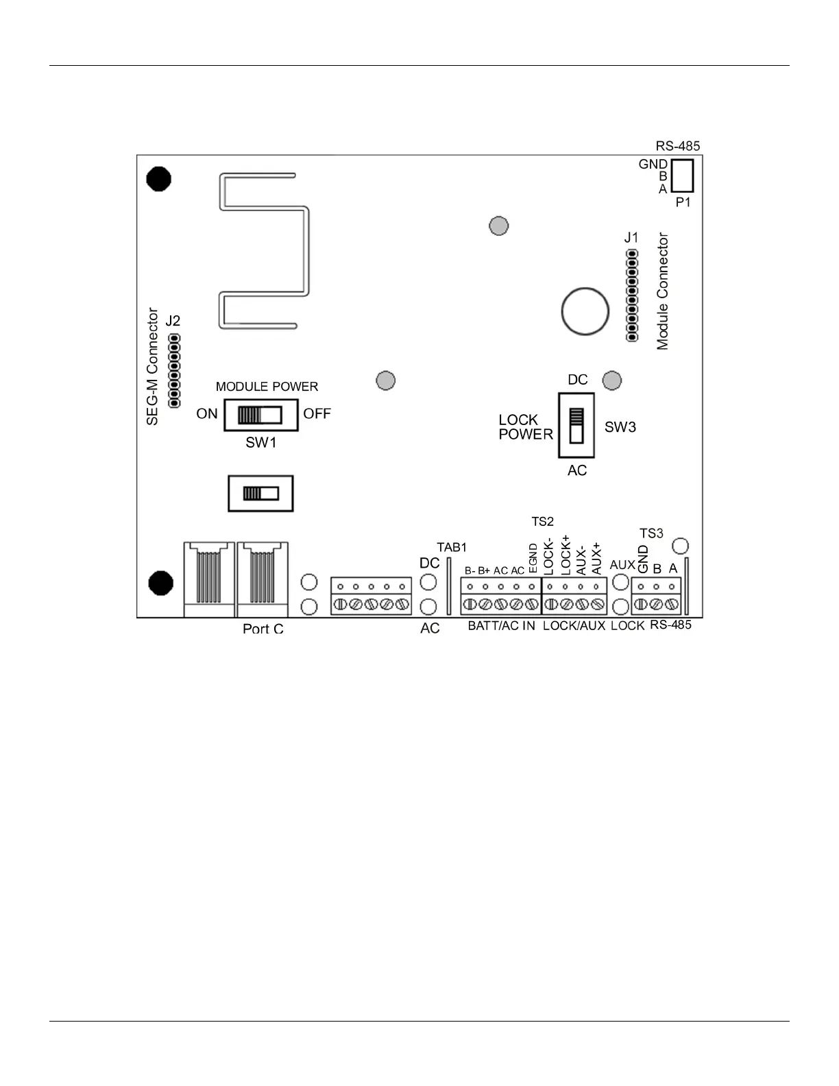
The diagram below shows the component locations and terminal connections on the Backplane.
Notes:
The Max 3 communicates to the PC via an RS-485 connection. For this connection use TS3 on the far right, bottom of the backplane.
The module is then connected to the backplane via connector P1.
Port C is used for configuring the SEG-M, when it's plugged onto J2 on the backplane.
Page 8 of 48 Document #: 6055672, Rev 1.0 D1c
Figure 2: MiniMax 3 Backplane Diagram
 Loading...