14
ifm Programming Manual ecomatmobile BasicController (CR0403) Runtime System V03.02 2015-04-01
System description Hardware description
>
Digital inputs
1015
7345
The binary input can be operated in following modes:
• binary input plus switching (BL) for positive sensor signal
• binary input minus switching (BH) for negative sensor signal
Depending on the device the binary inputs can configured differently. In addition to the protective
mechanisms against interference, the binary inputs are internally evaluated via an analogue stage.
This enables diagnosis of the input signals. But in the application software the switching signal is
directly available as bit information
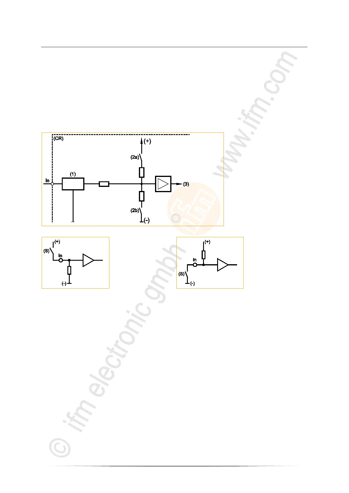
In = pin binary-input n
(CR) = device
(1) = input filter
(2a) = input minus switching
(2b) = input plus switching
(3) = voltage
Figure: basic circuit of binary input minus switching / plus switching for negative and positive sensor signals
In = pin binary-input n
(S) = sensor
In = pin binary-input n
(S) = sensor
Basic circuit of binary input plus switching (BL)
for positive sensor signal:
Input = open signal = low (GND)
Basic circuit of binary input minus switching (BH)
for negative sensor signal:
Input = open signal = high (supply)
For some of these inputs (→ data sheet) the potential can be selected to which it will be switched.