13
ifm Programming Manual ecomatmobile BasicController (CR0403) Runtime System V03.02 2015-04-01
System description Hardware description
>
3.2.2 Inputs (technology)
Analogue inputs ................................................................................................................................... 13
Digital inputs ........................................................................................................................................ 14
Input group I0 (IN0...IN3) ..................................................................................................................... 15
Input group I1 (IN4...IN7) ..................................................................................................................... 15
Input group I2 (IN8...IN11) ................................................................................................................... 17
14090
>
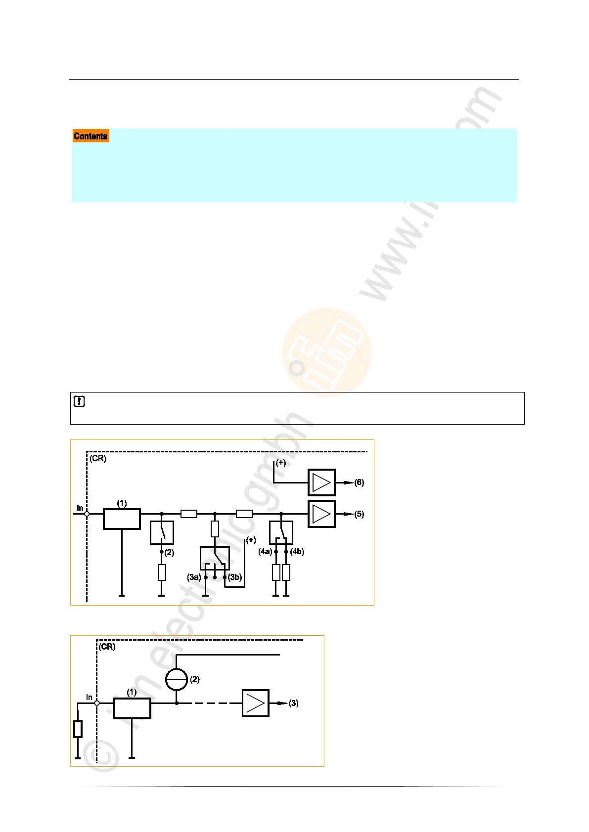
Analogue inputs
15444
The analogue inputs can be configured via the application program. The measuring range can be set
as follows:
• current input 0...20 mA
• voltage input 0...10 V
• voltage input 0...32 V
• resistance measurement 16...30 000 Ω (measurement to GND)
The voltage measurement can also be carried out ratiometrically (0...1000 ‰, adjustable via function
blocks). This means potentiometers or joysticks can be evaluated without additional reference voltage.
A fluctuation of the supply voltage has no influence on this measured value.
As an alternative, an analogue channel can also be evaluated binarily.
In case of ratiometric measurement the connected sensors should be supplied with VBBS of the
device. So, faulty measurements caused by offset voltage are avoided.
8971
In = pin multifunction input n
(CR) = device
(1) = input filter
(2) = analogue current measuring
(3a) = binary-input plus switching
(3b) = binary-input minus switching
(4a) = analogue voltage measuring 0...10 V
(4b) = analogue voltage measuring 0...32 V
(5) = voltage
(6) = reference voltage
Figure: principle block diagram multifunction input
8972
Figure: block diagram of the resistor survey input
In = pin resistor survey input n
(CR) = device
(1) = input filter
(2) = constant-current source
(3) = voltage