17
UK
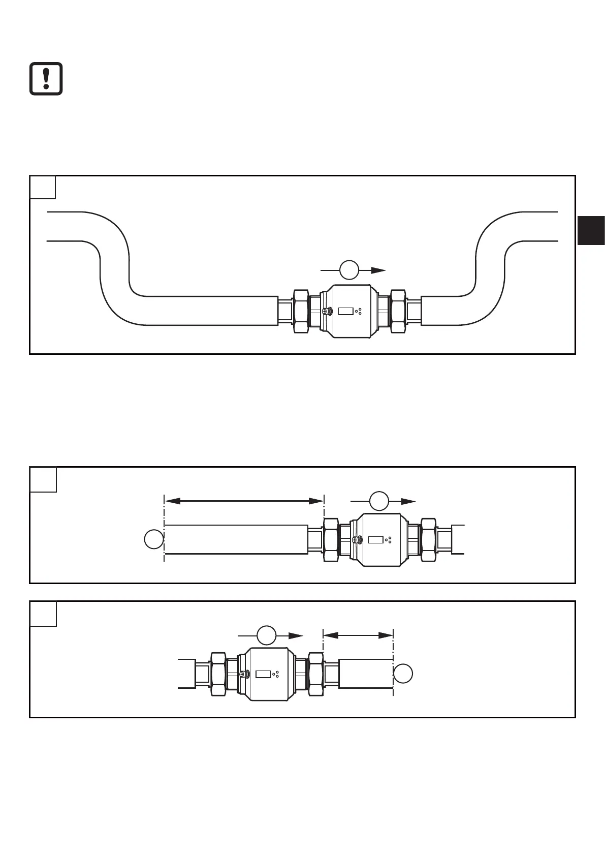
5 Installation
► Avoid deposits, accumulated gas and air in the pipe system�
5.1 Recommended installation locations
Example of an optimised installation:
F
1
► Install the unit so that the measuring pipe is completely filled�
► Arrange for inlet and outlet pipe lengths� Disturbances caused by bends,
valves, reductions, etc� are compensated for� It applies in particular: No shut-off
and control devices are allowed directly in front of the unit�
F
2 x D
S
3
F
S
5 x D
2
S = disturbance; D = pipe diameter; F = flow direction