7
UK
Both electrodes must be wetted by the medium� Otherwise the signal
[SEnS] for empty pipe is provided, if empty pipe detection is enabled�
4.2 Processing of the measured signals
The unit displays the current process values�
It generates 2 output signals according to the parameter setting�
OUT1/IO-Link: 5 selection options Parameter setting
- Switching signal for volumetric flow limit values (→10.3.1)
- or frequency signal for volumetric flow quantity (→10.3.4)
- or pulse signal for quantity meter (→10.4.1)
- or switching signal for preset counter (→10.4.2)
- or switching signal for empty pipe detection (→10.6.9)
OUT2: 6 selection options Parameter setting
- Switching signal for volumetric flow limit values (→10.3.2)
- or switching signal for temperature limit value (→10.5.1)
- or analogue signal for volumetric flow quantity (→10.3.3)
- or analogue signal for temperature (→10.5.2)
- or input for external reset signal (InD) (→10.4.6)
- or switching signal for empty pipe detection (→10.6.9)
4.3 Volumetric flow monitoring
4.3.1 Volumetric flow quantity
The signals for measuring the volumetric flow quantity can be provided as follows:
1� Two switching signals for volumetric flow quantity limit values on output 1 and
output2.Ontheswitchingfunctions→4.7.
2� Afrequencysignal(10Hz...10kHz)onoutput1.Onthefrequencyfunctions→
4�9�
3� An analogue signal (4���20 mA or 0���10 V) on output 2� On the analogue
functions→4.8.
4.3.2 Direction of flow
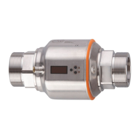
In addition to the flow velocity, the unit also detects the flow direction� An arrow on
the unit indicates the positive flow direction�
Theflowdirectioncanbeinversed(→10.6.3).