Chapter 2: Pre-Installation Considerations
RTMS Echo User Guide ©2019 Image Sensing Systems Inc. 2-7
Providing a Proper Ground
Providing a low resistance earth ground connection is essential to achieving
effective surge protection. Total resistance from the protected circuit to the
earth should be <5ohms.
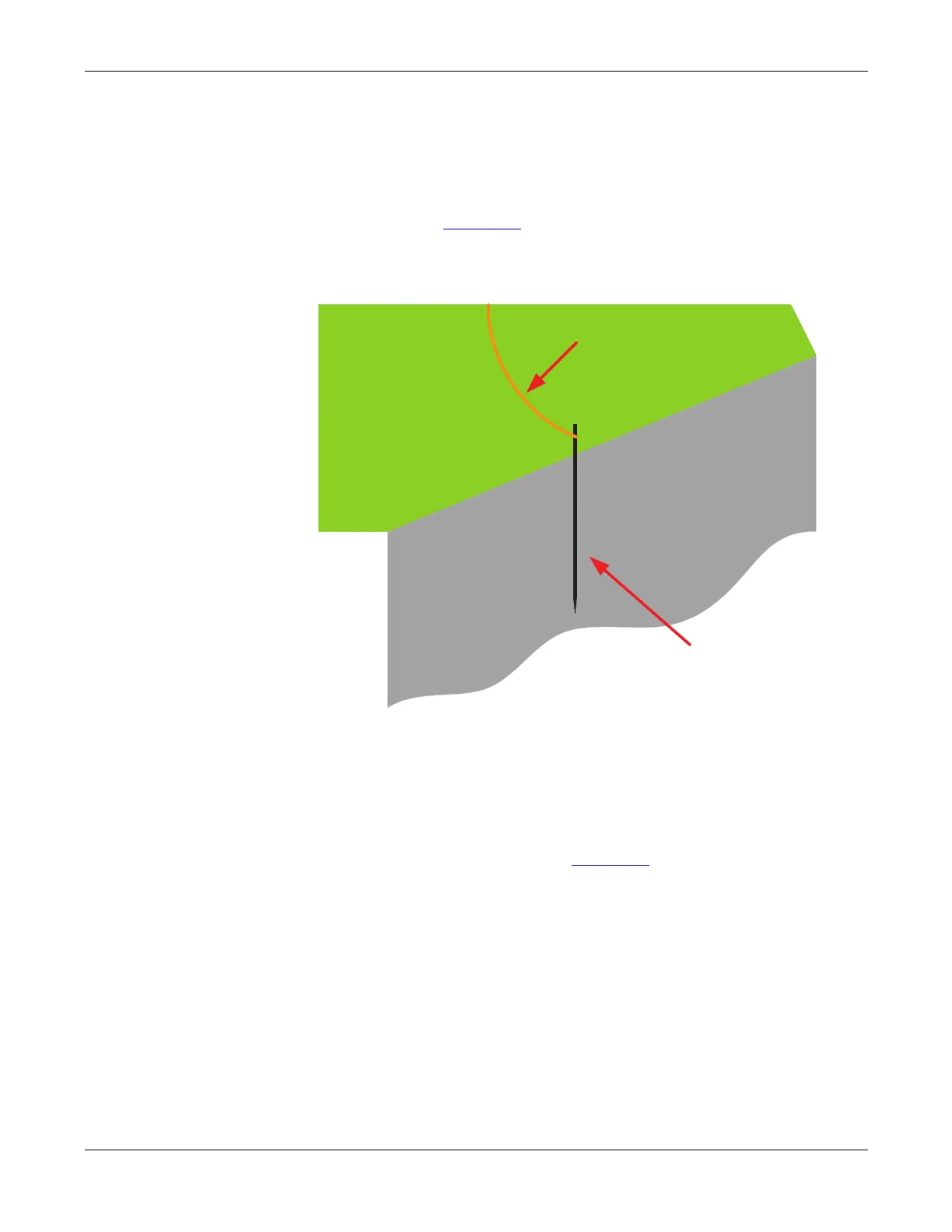
A grounding rod (see Figure 2-7
) should be at least 1.83 m (6 ft) in length and
placed as close as possible to the base of the RTMS Echo mounting pole. The
grounding conductor should be flexible copper braid or copper wire 12AWG or
larger.
Figure 2-7: Earth Ground Connection
The earth grounding rod, together with proper ground of the breakout box, and
surge protecting devices installed in close proximity of the mounting pole,
create a barrier or ‘sink hole’ for any charges and surges coming towards the
sensor from the surrounding area (see Figure 2-8
). These charges and surges
may be caused by industrial noise, power surges, or lightning.
Grounding conductor
6 foot copper rod