EasyManuals Logo

IMC C SERIES User Manual

IMC C SERIES
185 pages
To Next Page IconTo Next Page
To Previous Page IconTo Previous Page
Page #145 background imageLoading...
Page #145 background image
© 2018 imc Test & Measurement GmbH
imc C-SERIES - Manual, Version 4 R 3 - 2018-10-19
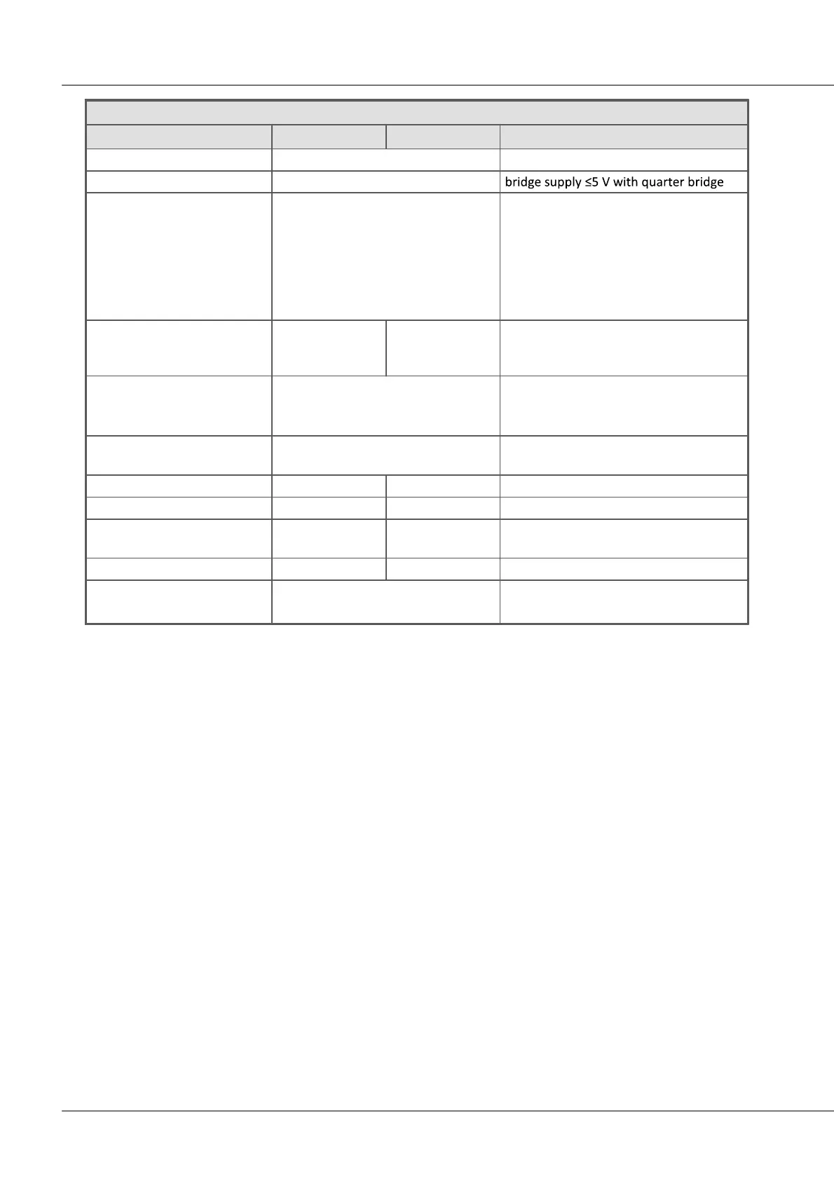
145CS-5008-FD, CL-5016-FD analog inputs
Bridge measurement
Parameter
Value typ.
min. / max.
Remarks
Mode
DC
Measurement modes
full-, half-, quarter bridge
Input ranges
±1000 mV/V, ±500 mV/V,
±200 mV/V, ±100 mV/V
bridge supply: 10 V
... ±0.5 mV/V
bridge supply: 5 V
... ±1 mV/V
bridge supply: 2.5 V
... ±2 mV/V
(as an option)
bridge supply: 1 V
... ±5 mV/V
(as an option)
Bridge excitation voltage
(as an option)
10 V
5 V
(2.5 V and 1 V)
±0.5%
±0.5%
The actual value will be dynamically
captured and compensated for in bridge
mode.
Min. bridge impedance
Max. bridge impedance
120 Ω, 10 mH full bridge
60 Ω, 10 mH half bridge
5 kΩ
Internal quarter bridge
completion
120 Ω, 350
internal, switchable per software
Input impedance
20 MΩ
±1 %
differential, full bridge
Gain error
0.02%
0.05%
of reading
Offset error
0.01%
0.02%
of input range after automatic bridge
balancing
automatic shunt calibration
0.5 mV/V
±0.2%
for 120 and 350 Ω
Cable resistance for bridges
(without return line)
<6 Ω
<12 Ω
10 V excitation 120
5 V excitation 120

Table of Contents

Questions and Answers:

Question and Answer IconNeed help?

Do you have a question about the IMC C SERIES and is the answer not in the manual?

IMC C SERIES Specifications

General IconGeneral
BrandIMC
ModelC SERIES
CategoryMeasuring Instruments
LanguageEnglish

Related product manuals