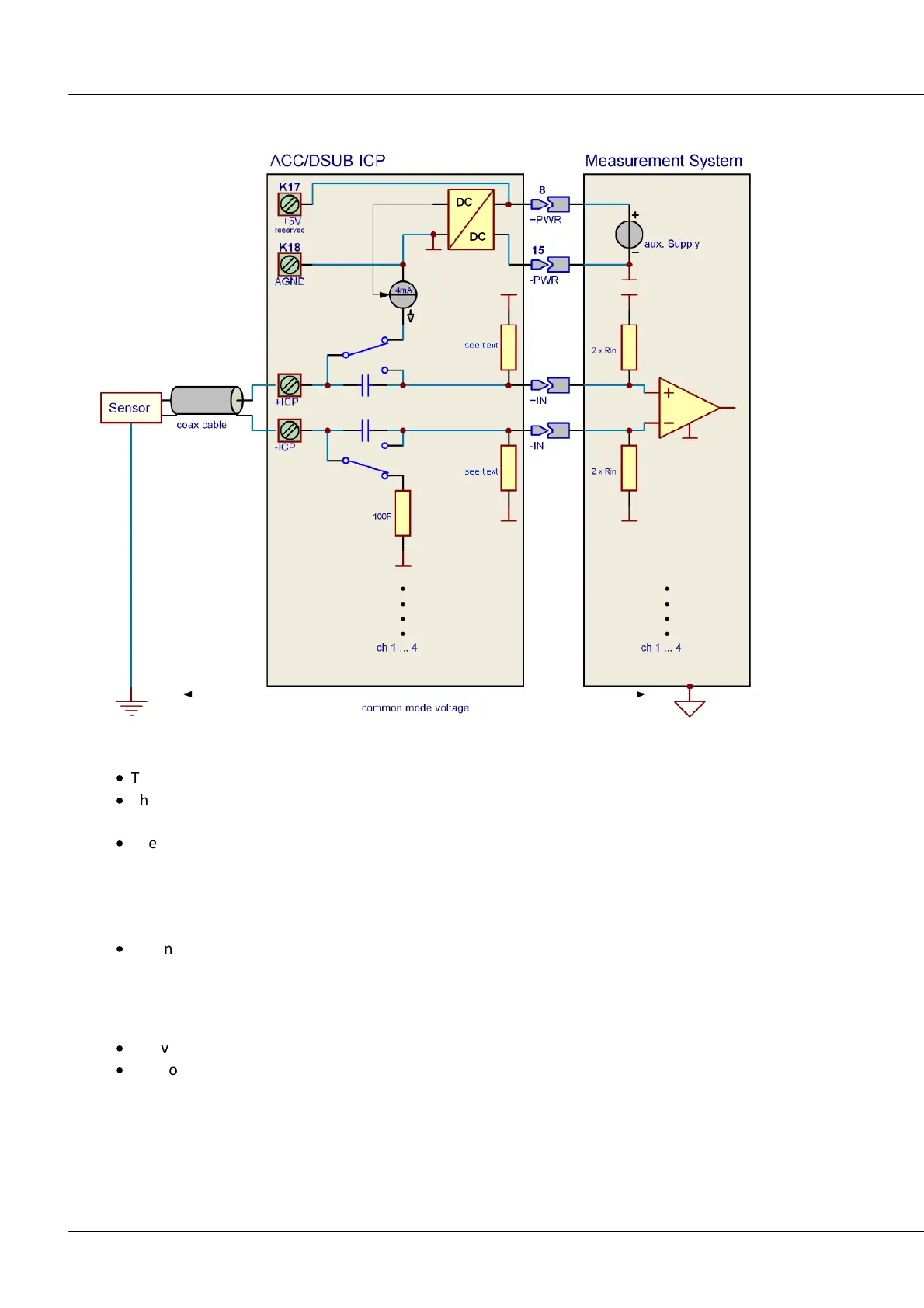
DIP-Switch position ICP (DIP-Switch inside of the Expansion-connector):
·
The AC-coupling is already provided by the ICP-plug, the voltage channel is DC-coupled.
·
The measurement range must be adapted to the signal's AC-component, it can be adjusted within
the range: ±5 V to ±250 mV
·
The combination of the built-in coupling capacitor (2 x 220 nF corresponding to 110 nF diff.) with
the impedance of the IEPE/ICP-plug (2 MΩ diff.) and the input impedance constitutes a high-pass
filter. When connecting the plug or sensor, be aware of the transients experienced by this high-pass
filter, caused by the sensor's DC-offset (typ. +12 V). It is necessary to wait until this phenomenon
decays and the measured signal is offset-free!
·
When the ICP-expansion plug is used, a considerable offset can occur (in spite of AC-coupling),
which can be traced to the (DC-) input currents in conjunction with the voltage amplifier's DC input
impedance. This remainder, too, can be compensated by high-pass filtering with imc Online FAMOS.
DIP-Switch position Volt (DIP-Switch inside of the Expansion-connector):
·
The voltage channel is DC-coupled, the current source de-coupled.
·
The voltage channel's input impedance is reduced by parallel connection with the IEPE/ICP-plug's
impedance.