© 2018 imc Test & Measurement GmbH
imc C-SERIES - Manual, Version 4 R 3 - 2018-10-19
54 Properties of the imc C-SERIES
The voltage amplifiers' different input impedance values (with / without input divider) depend on the
voltage range selected. The resulting high-pass cutoff frequencies and the time necessary for the 12 V-
offset to decay to 10 µV are shown.
In terms of the shielding and grounding of the connected IEPE/ICP-sensor, note:
·
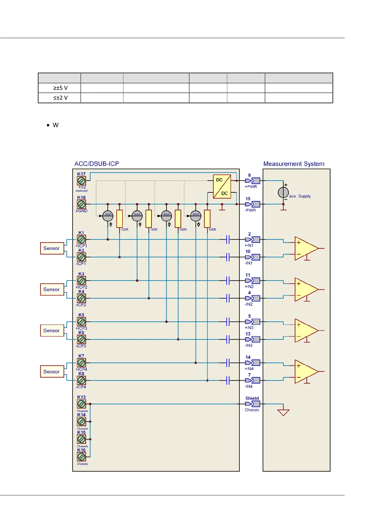
We recommend using multicore, shielded cable, where the shielding (at the plug) is connected to
the plug "CHASSIS", or can be connected to the pull-relief brace in the plug.
The following circuit schematic display an entire plug. The DIP switches are not included in order to
achieve a more simple schematic.