© 2018 imc Test & Measurement GmbH
imc C-SERIES - Manual, Version 4 R 3 - 2018-10-19
67Hardware configuration of all devices
5.1.1.3.2 Comparator conditioning
The incremental encoder channels' special properties make special demands on the signal quality: The
very high time-resolution of the detector or counter means that even extremely short impulses which
sampling measurement procedures (as at the digital inputs) would miss are captured and evaluated.
Therefore the digital signals must have clean edges in order not to result in distorted measurements.
Missed pulses or bounces could otherwise lead to drop-outs in the time measurements, or enormous
"peaks" in the rpm-measurements.
Simple sensors such as those based on induction or photosensitive relays often emit only unconditioned
analog signals which must be evaluated in terms of a threshold value condition. Furthermore long cables,
ground loops or interference, can make the processing of even conditioned encoder signals (such as TTL-
levels) difficult. The device, however, can counteract this using its special three-step conditioning unit.
To begin with, a high-impedance differential amplifier (±10 V range, 100 k
W
) enables reliable
measurement from a sensor even along a long cable, as well as effective suppression of common mode
interference and ground loops. A (configurable) filter (in preparation) at the next stage offers additional
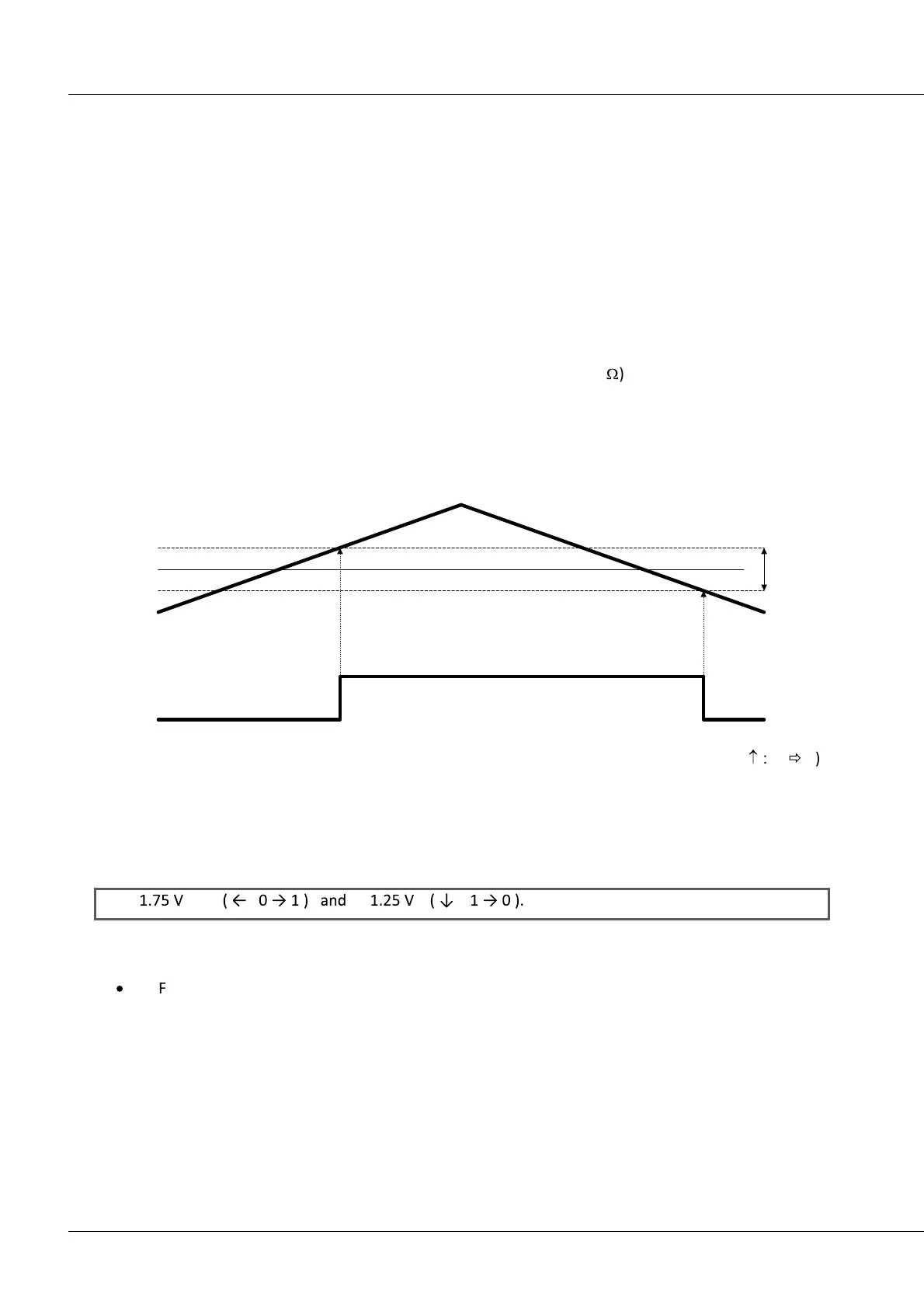
suppression of interference, adapted to the measurement set-up. Finally, a comparator with configurable
threshold and hysteresis acts as a digital detector. The (configurable) hysteresis is an extra tool for
suppressing noise:
VREF VHYST
INC
(digital)
IN
(analog)
IN > VREF
+
VHYST/2 IN < VREF
-
VHYST/2
If the analog signal exceeds the threshold VREF + VHYST/2. the digital signal changes its state (
: 0
ð
1)
and at the same time reduces the threshold which must be crossed in order to change the state back to 0
by the amount VHYST (new threshold: VREF - VHYST/2). The magnitude of the hysteresis therefore
represents the maximum level of noise and interference that would not cause a spurious transition.
The threshold VREF is set to 1,5 V, the hysteresis VHYST is 0,5 V.
State transitions are therefore detected at the signal amplitudes:
In future device versions, the threshold and hysteresis will be globally adjustable for all four channels
within the range:
·
VREF = ±10 V VHYST = +100 mV .. +4 V
Corner frequencies of the (2-pole) low-pass filter will be jointly configurable for both of a channel's tracks
to the values: Low-pass filter: 20 kHz, 2 kHz, 200 Hz