© 2018 imc Test & Measurement GmbH
imc C-SERIES - Manual, Version 4 R 3 - 2018-10-19
68 Device description
5.1.1.3.3 Structure
Complete conditioning with individual differential inputs is provided for 4 tracks: they can be used for
four channels with one-signal-encoders or for two channels with two-signal encoders.
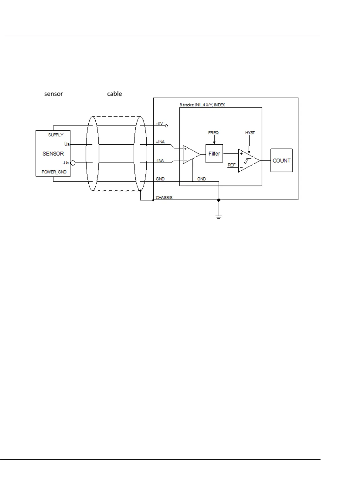
Block schematic
Dual track encoders (quadrature encoders) emit two signals offset by 90° of phase, the tracks A and B. By
evaluating the phase information between the A and B-track, the direction of turning can be determined.
If the corresponding encoder type is selected, this functionality is supported. The actual time or
frequency information, however, is derived exclusively from the A-track!
Like the other channels, the Index-channel is fully conditioned. If its function is activated, it can take
effect on all four channels.
5.1.1.3.4 Channel assignment
The connector used is the ACC/DSUB(M)-ENC-4. This connector enable all four incremental counters to
be connected at the same terminal.
As a prerequisite for the input differential amplifier to find the correct working point, the sensor must be
ground referenced, i.e. it must have low resistance to ground (GND, CHASSIS, PE). This is not to be
confused with the sensor’s common mode voltage, which may be up to +25 V/-12 V (even for the –IN
input!). It also does not matter that a differential measurement is configured for the high-impedance
differential input. If this electrical connection to the system ground (CHASSIS) does not exist initially
because the sensor is electrically isolated, then such a connection must be set up, for instance in the
form of a wire jumper between the sensor’s GND and POWER_GND contacts!
The 5 V (max. 100 mA, 300 mA upon request) supply voltage which the module provides at the terminals
+5 V and GND can be used to power the sensors. If more voltage or supply power is needed, the sensor
must be supplied externally, which means that it is absolutely necessary to ensure that this supply
voltage is referenced to system ground!