© 2018 imc Test & Measurement GmbH
imc C-SERIES - Manual, Version 4 R 3 - 2018-10-19
70 Device description
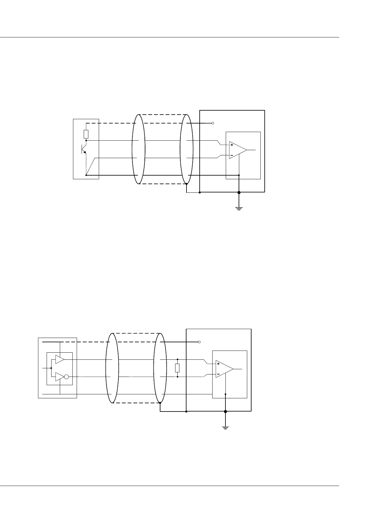
5.1.1.3.7.1 Connection: Open-Collector Sensor
Simple rotary encoder sensors are often designed as an Open-Collector stage which outputs a signal
which ranges between the states 0 V and SUPPLY. In this case, the switching threshold should be set to
half the SUPPLY voltage:
sensor with open-collector output
5.1.1.3.7.2 Connection: Sensors with RS422 differential line drivers
Commercially available rotary encoders are often equipped with differential line drivers, for instance as
per the EIA-standard RS422. These deliver a complementary (inverse) TTL-level signal for each track. The
sensor's data are evaluated differentially between the complementary outputs. The threshold to select is
0 V, since the differential evaluation results in a bipolar zero-symmetric signal: 3.8 V to 5 V (HIGH) or –
3.8 V to 5 V (LOW). Ground loops as pure common mode interference are suppressed to the greatest
possible extent.
The illustration below shows the circuiting. The reflection response and thus the signal quality can be
further improved by using terminator resistors.
sensor with RS422 differential output