© 2018 imc Test & Measurement GmbH
imc C-SERIES - Manual, Version 4 R 3 - 2018-10-19
71Hardware configuration of all devices
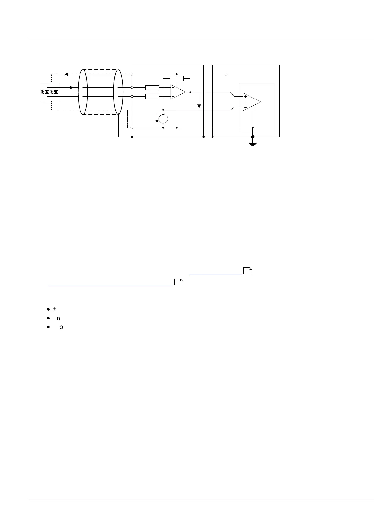
5.1.1.3.7.3 Connection: Sensors with current signals
GND
-INA
+INA
+5V
CHASSIS
+/-10V
cablesensor
ENC-4
+I
R
2.5V
500R
500R
+INA
-INA
ACC/DSUB-ENC4-IU
-I
Vout
Vout = Va-V0 = -R*I
INDEX: R = 100k
IN_AB[1..4]: R = 200k
I = 11µA_pkpk = +/-5.5µA (typ.)
Vout = 1.1V sin(wt), 2.2Vpkpk
(min. 0.7V, max. 1.6V)
V0
Va
I_supply: max. 170mA / D SUB !
+5V
GND
CHASSIS
I_supply
For a rotational encoder working with current signals, the current/ voltage terminal ACC/DSUB-ENC-4-IU
can be used.
It is possible to power the sensor from the ENC-4 module. The pertinent specifications are:
max. supply current: 320 mA
typ. encoder with 11 µA
ss
signals:
Heidenhain ROD 456, current c: max. 85 mA per (2-signal) encoder
5.1.2 Analog outputs
The analog outputs DAC 01 to 04 provide 4 analog output channels to be used as dynamic control and
actuator signals. The outputs can be defined as the results of calculations performed by imc Online
FAMOS on data from combinations of measurement channels.
The pin configuration of the corresponding DSUB-15: ACC/DSUBM-DAC4 .
The technical specification of the module DAC-4 .
Highlights
·
±10 V level at max. ±10 mA driver capability and 250 Ω load
·
ensured startup level 0 V without undefined transient states
·
short-circuit protected against ground.
170
155