18
INSTALLER
USERMAINTENANCE TECHNICIAN
TECHNICAL DATA
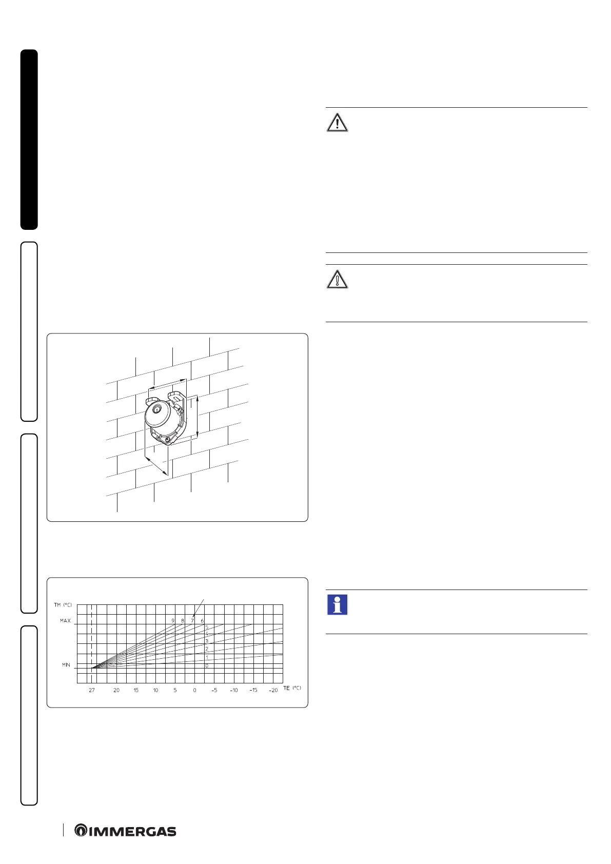
1.11 EXTERNAL TEMPERATURE PROBE
OPTIONAL
e boiler is designed for the application of the external tempera-
ture probe (Fig. 10), which is available as an optional kit.
Refer to the relative instruction sheet for positioning of the exter-
nal probe.
e probe can be connected directly to the boiler electrical system
and allows the max. system ow temperature to be automatically
decreased when the external temperature increases, in order to
adjust the heat supplied to the system according to the change in
external temperature.
e external probe always operates when connected, regardless of
the presence or type of room chrono-thermostat used and can
work in combination with Immergas chrono-thermostats.
e correlation between system ow temperature and external
temperature is determined by the position of the central heating
selector switch on the boiler control panel (or on the CAR
V2
con-
trol panel if connected to the boiler) according to the curves
shown in the diagram (Fig. 11).
e electric connection of the external probe must be made on
terminals 38 and 39 on the terminal board in the boiler control
panel (Fig. 40).
45
31
58
10
Correction law of the ow temperature depending on the
external temperature and user adjustment of the central
heating temperature.
11
* Position of the central heating temperature control.
1.12 IMMERGAS FLUE SYSTEMS
Immergas supplies various solutions separately from the boilers
regarding the installation of air intake terminals and ue exhaust,
which are fundamental for boiler operation.
e boiler must be installed with an original Immergas
“Green Range” inspectionable air intake system and vis-
ible ue gas extraction system made of plastic, with the
exception of the C
6
conguration, as required by the
regulations in force and by the product’s approval. is
ue system can be identied by the specic identica-
tion mark bearing the following indication: “only for
condensation boilers”.
For non-original ue system, refer to the technical data
of the appliance.
e plastic pipes cannot be installed outdoors, for tracts
longer than 40 cm, without suitable protection from UV
rays and other atmospheric agents.
Resistance factors and equivalent lengths
Each ue component has a Resistance Factor based on experimen-
tal tests and specied in the table below.
e Resistance Factor for individual components is independent
from the type of boiler on which it is installed and has a dimen-
sionless size.
It is however, conditioned by the temperature of the uids that
pass through the pipe and therefore, varies according to applica-
tions for air intake or ue exhaust.
Each single component has a resistance corresponding to a cer-
tain length in metres of pipe of the same diameter; the so-called
equivalent length, can be obtained from the ratio between the rel-
ative Resistance Factors.
All boilers have an experimentally obtainable maximum Resist-
ance Factor equal to 100.
e maximum Resistance Factor allowed corresponds to the re-
sistance encountered with the maximum allowed pipe length for
each type of Terminal Kit.
is information allows calculations to be made to verify the pos-
sibility of setting up various ue congurations.
To dimension the ue ducting using commercial com-
ponents, refer to the table of combustion parameters
(Par. 4.2).