55
INSTALLER
USERMAINTENANCE TECHNICIAN
TECHNICAL DATA
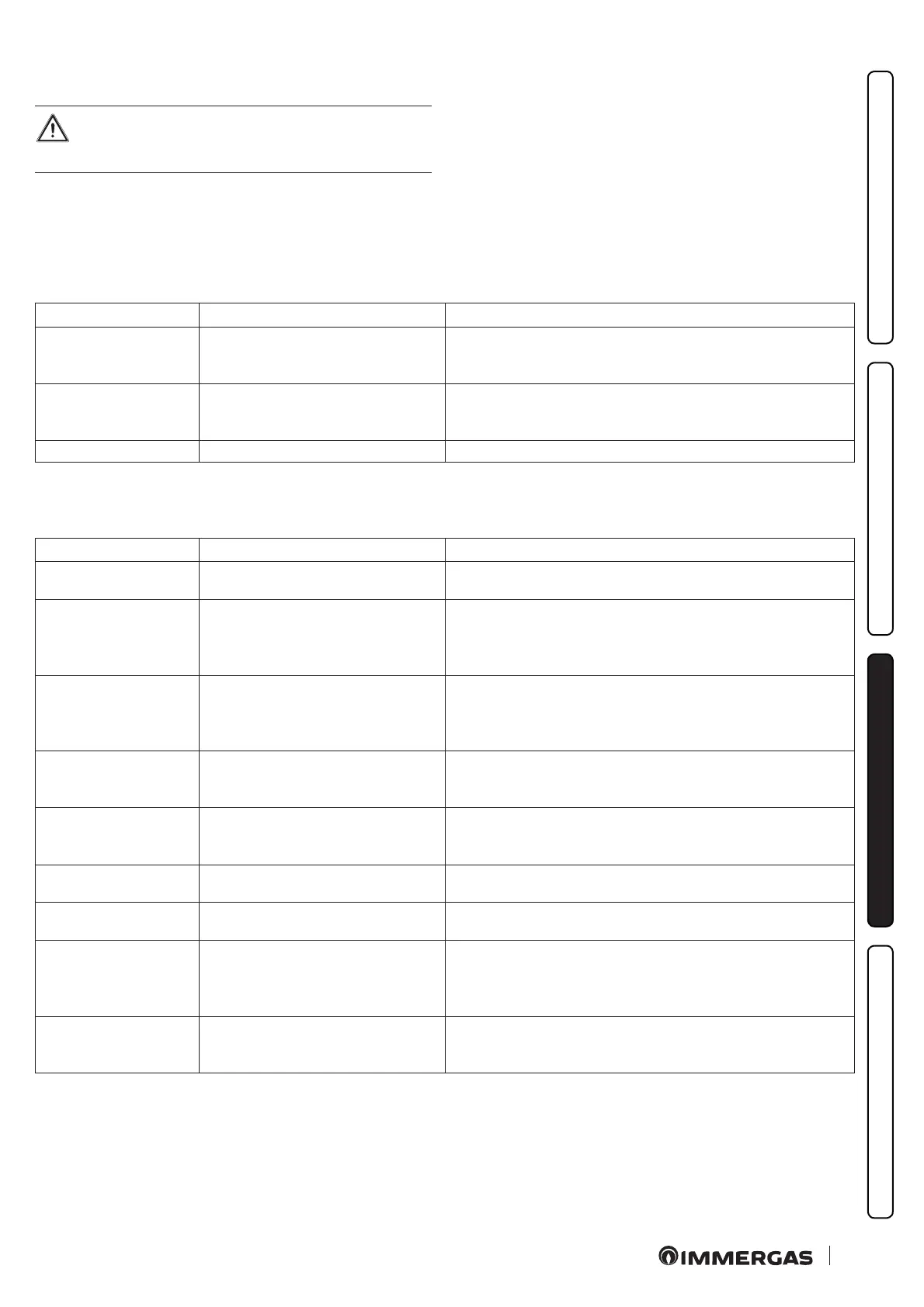
3.6 TROUBLESHOOTING
Maintenance operations must be carried out by an au-
thorised company (e.g. Authorised Technical Assis-
tance Service).
ere can be three possible causes for this anomaly:
Red pump LED
Trouble Possible causes Solutions
Low power supply voltage
Aer about 2 seconds, the LED switches
from green to red and the pump stops.
Wait for the power supply voltage to rise; when the pump restarts, the LED
will turn green again with a delay of about one second. Note: e ow rate
decreases as the supply voltage decreases.
Rotor seized
Powering the pump with the rotor seized,
aer about 4 seconds the LED switches
from green to red,
Carefully act on the screw in the middle of the head to manually release
the cranksha; circulation starts up immediately aer the rotor is re-
leased and the LED switches from red to green aer about 10 seconds.
Electrical error Check that there is no fault on the pump (on its wiring or electronics).
Trouble Possible causes Solutions
Smell of gas
Caused by leakage from gas circuit pipe-
lines.
Check sealing eciency of gas intake circuit.
Repeated ignition blocks No gas. Condensate drain clogged.
Check the presence of pressure in the network and that the gas adduction
cock is open. Restore/release the function of the condensate drain, check-
ing that the condensate has not aected: combustion components, fan
and gas valve. Check the function of the condensate sensor.
Irregular combustion or
noisiness
Dirty burner, clogged primary heat ex-
changer, incorrect combustion parame-
ters, intake-exhaust terminal not correctly
installed.
Check the indicated components.
Non-optimal ignition of
rst ignitions of the
burner.
e rst ignitions of the burner (aer cali-
bration) may not be optimal.
e system automatically adjusts the burner ignition until the best igni-
tion conditions are found.
Frequent trips of the
overheating safety device
thermostat function.
Lack of water in the boiler, poor water cir-
culation in the system or blocked circulat-
ing pump (Par. 1.29 , 1.30).
Check on the pressure gauge that the system pressure is within estab-
lished limits. Check that the radiator valves are not closed and also the
functionality of the pump.
Siphon blocked
Di rt or combustion products deposited i n-
side.
Check that there are no residues of material blocking the ow of conden-
sate.
Condensing heat
exchanger clogged
Siphon and/or duct between condensing
exchanger and siphon clogging.
Check that there are no residues of material blocking the ow of conden-
sate.
Abnormal noises in the
system
Air in the system.
Check the opening of the cap of the air vent valve (Par. 1.32). Make sure
the system pressure and expansion vessel pre-charge values are within the
set limits. e factory-set pressure values of the expansion vessel must be
1.0 bar, the value of system pressure must be between 1 and 1.2 bar.
Abnormal noises in the
condensation module
Air in the module.
Use the manual air vent valve (Par. 1.32) to eliminate any air present in
the condensation module. When the operation has been performed, close
the manual vent valve.