16
INSTALLER
USERMAINTENANCE TECHNICIAN
TECHNICAL DATA
1.9 ELECTRICAL CONNECTION
e appliance has an IPX5D protection degree; electrical safety of
the appliance is achieved only when it is connected properly to an
ecient earthing system, as specied by current safety standards.
e manufacturer declines any responsibility for dam-
age or physical injury caused by failure to connect the
boiler to an ecient earthing system or failure to comply
with the IEC reference standards.
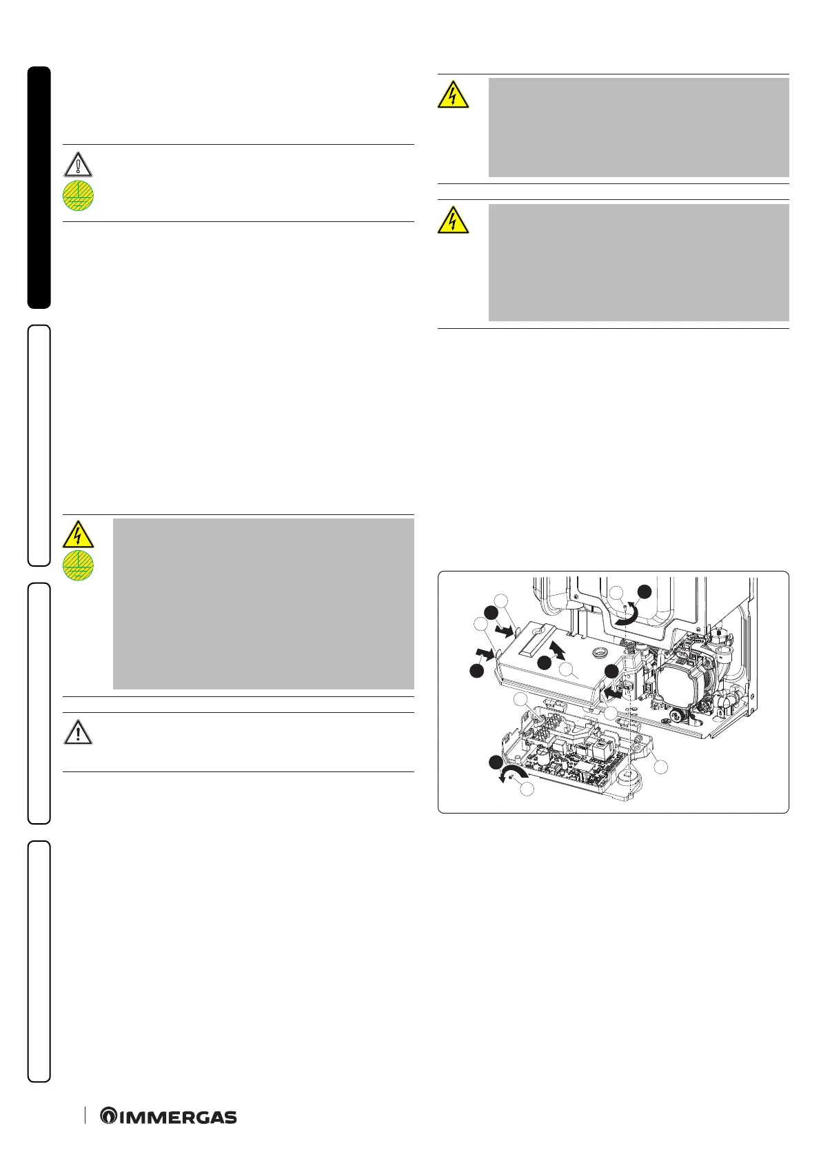
Open the control panel connections compartment
(Fig. 8)
To carry out electrical connections, all you have to do is open the
connections compartment as follows.
Remove the casing:
1. Loosen the screw (a) at the bottom.
2. Rotate the control panel and then loosen the screw (b) that se-
cures the control panel’s (d) cover.
3. Press the three hooks (c) on the cover (d).
4. Remove the cover (d) from the control panel (e).
At this point, it is possible to access the terminal board (f).
Also ensure that the electrical installation corresponds to maxi-
mum absorbed power specications as shown on the boiler data
nameplate.
e boilers are supplied complete with a “Y” type H 05 VVF
3 x 0.75 mm
2
power supply cable, without plug.
e power supply cable must be connect-
ed to a 230V ±10% / 50Hz mains supply
respecting L-N polarity and earth con-
nection; this network must also have a
multi-pole circuit breaker with class III
overvoltage category in compliance with
installation regulations.
No appliance pipes must ever be used to earth the elec-
tric system or telephone lines.
To protect from possible dispersions of
DC voltage, it is necessary to provide a
type A dierential safety device.
If the power cable is damaged, contact a
qualied company (e.g. the Authorised
Technical Assistance Centre) for its re-
placement to avoid a hazard.
e power cable must follow the prescribed route (Par. 1.6);
If the network fuse on the connection terminal board needs re-
placing, this must also be done by qualied personnel: use a 3.15 A
fast fuse.
For the main power supply to the appliance, never use adapters,
multiple sockets or extension leads.
Installation with system operating at direct low temperature
e boiler can directly supply a low-temperature system by set-
ting the ow temperature adjustment range “t0” and “t1”
(Par. 3.13). In this case, it is suitable to add a specic safety kit (opt-
tional) made up of a thermostat (with adjustable temperature).
e thermostat must be positioned on the system ow pipe at a
distance of at least 2 metres from the boiler.
1
a
3
c
d
b
2
c
c
3
3
4
e
f
8