11
INSTALLER
USERMAINTENANCE TECHNICIAN
TECHNICAL DATA
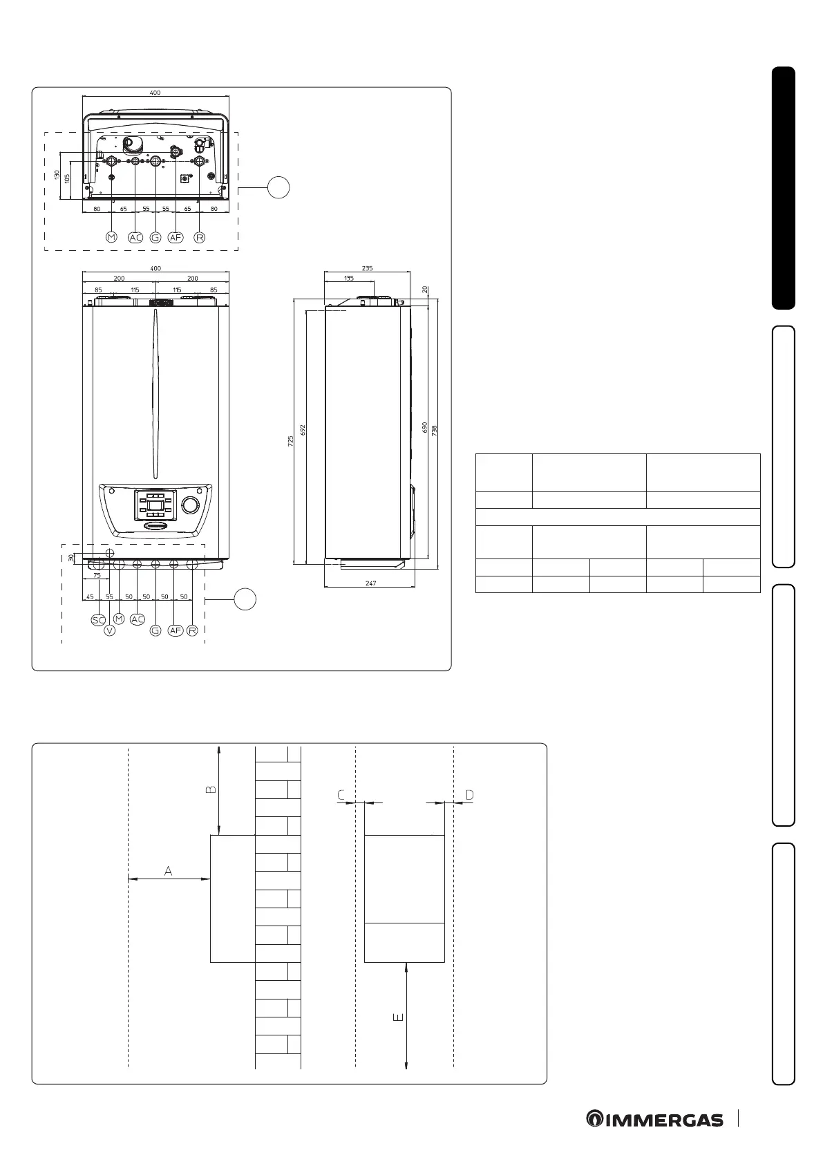
1.2 MAIN DIMENSIONS
1
2
2
Key (Fig. 2):
V - Electric connection
M - System ow
SC - Condensate drain (minimum internal diame-
ter Ø 13 mm)
AC - Domestic hot water outlet
G - Gas supply
AF - Domestic hot water inlet
R - System return
1 - Boiler direct hydraulic connection
2 - Wall-mounted hydraulic connection with Im-
mergas DIN template
Height
(mm)
Width
(mm)
Depth
(mm)
738 400 247
CONNECTIONS
GAS
DOMESTIC HOT
WATER
SYSTEM
G AC AF R M
3/4" 1/2" 1/2" 3/4" 3/4"
1.3 MINIMUM INSTALLATION DISTANCES
3
Key (Fig. 3):
A - 450 mm
B - 350 mm
C - 30 mm
D - 30 mm
E - 350 mm